
2. Remove the wheel.
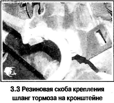
3. Remove the brake disc (Chapter 9). Disconnect the brake hose from the bracket on the suspension strut (see photo).
4. Turn away a nut of a semiaxis, holding a nave the lever for 2 temporarily screwed in bolts.
5. Release a nut of a tip of steering draft and press out a tip from the lever of a rotary fist. Disconnect the tie rod end.
6. Turn away a coupling bolt of a collar of a spherical support.
7. Expand the ball joint collar with a screwdriver or chisel.
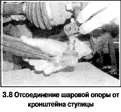
8. Remove the ball joint from the hub bracket by pressing it out with a pry bar. Pull the hub bracket and disconnect from the lever (see photo).
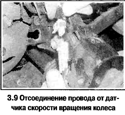
9. On models with ABS, disconnect the wire from the wheel speed sensor (see photo).
10. Using a puller, remove the hub bracket with the brake shield.
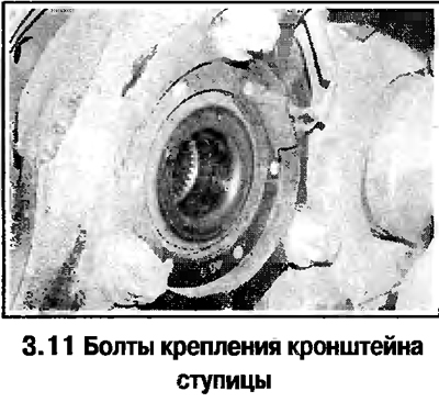
11. Mark the position of the brake shield and the hub bracket and disassemble the assembly by unscrewing the 3 bolts from the back of the bracket (see photo).
12. The hub with the bearing is a non-separable unit and can be changed entirely.
13. Assembly is carried out in the reverse order. Tighten fastenings of a spherical support with the set moment. Tighten the axle nut in several stages (see technical data) and lock.
Visitor comments