


2. Remove the trim of the corresponding door (see Section 19).
3. Separate the insulating film from the door frame as much as necessary to clear access to the relevant parts.
4. On all models except Hatchback (GTS), remove the rear door glass guide.
5. Press the locking bracket and separate the rod from the door handle (see accompanying illustration).
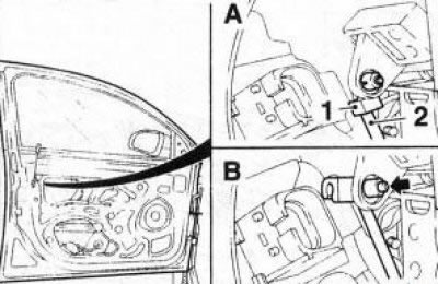
17.5 Disconnecting the rod (2) from the door handle (using the example of the rear side door lock): 1. Locking bracket
6. On the driver's door, remove the outer door handle with the support bracket (see Section 18).
7. Remove the 3 screws on the rear end wall of the door and separate the lock from the door frame (see accompanying illustration).
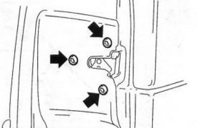
17.7 Screws (indicated by arrows) side door lock fasteners
8. On the rear door, unscrew the screw and remove the drive cable holder (see accompanying illustration) from the door frame. Disconnect the cable core from the lock release button pivot lever.
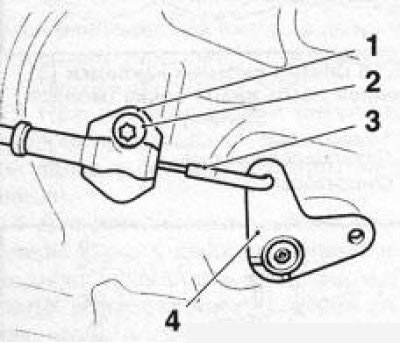
17.8 Remove the screw (2), remove the holder (1) and disconnect the core (3) of the drive cable from the rotary lever (4) of the door lock release button
9. Using a screwdriver, press the lock and disconnect the electrical connector of the door lock electric motor (see accompanying illustration).
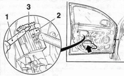
17.9 Lock (3) of the connector (2) of the electrical wiring of the door lock electric motor - the arrow indicates the hole for removing the lock 1 Screwdriver
10. On the front door, use a plastic wedge to separate the wiring harness from the lock.
11. Remove the lock with the cable from the door frame.
Note: On the front door, the lock is removed from the lower hole (see illustration 17.9).
12. Press the drive cable holder lock and separate the holder and then the cable core from the lock (see accompanying illustration).
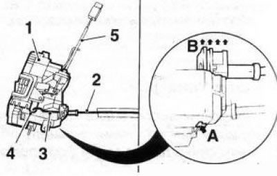
17.12 Fastening the drive cable (2) and the rod (5) of the lock release button (using the front door as an example): 1. Castle; 3. Rope core; 4. Core attachment point; Arrow A - Holder lock; Arrows B - Direction of holder removal
Note: On the rear door, the cable for the lock release button is disconnected in a similar manner.
13. On the front door, separate the lock release button rod (see illustration 17.12).
14. Installation is performed in the reverse order of removal. Pay attention to the reliability of the cables and rods. Without slamming the door, check the operation of the locking mechanism.
Visitor comments