
Harmonious operation of nodes
The fuel pump delivers gasoline under pressure to the pressure regulator. This ensures that the pressure on the injection valve is constant (0.75 bar).
The control unit receives information about the operation of the engine through impulses about the number of revolutions from the ignition, about the resistance indicators from the throttle potentiometer (throttle position), as well as voltage pulses from the intake manifold pressure sensor. Based on this, the control unit draws conclusions about the state of the load on the engine and mixes the required amount of fuel into the intake air - through the injection valve. With this dosage, the ratio of fuel and air l = 1 is considered as optimal for the operation of the catalytic converter. This ratio must be corrected depending on the signal from the lambda probe (see chapter «Reducing the toxicity of exhaust gases»).
The injection valve can only open and close, but not meter the amount of fuel. Therefore, the amount of fuel is varied by means of the injection duration. This happens as follows: with each ignition pulse of the ignition system, the valve injects fuel once. If little fuel is needed, the valve opens for a very short time, often less than one thousandth of a second.
On the contrary, if the engine needs an increased amount of fuel (full load, cold engine), then with this pulse the injection duration is longer. Of course, this applies to every ignition pulse.
Starting a cold engine
The control unit receives information about the engine temperature from the coolant temperature sensor. The colder the engine (= lower coolant temperature), the longer the fuel injection time must be to obtain an enriched combustible mixture.
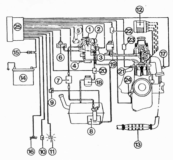
Here is a schematic representation of the Multec central injection system:
1 - injection valve;
2 - fuel pressure regulator;
3 - idle stepper motor;
4 - coolant temperature sensor;
5 - throttle potentiometer;
6 - pressure sensor in the intake manifold;
7 - fuel filter;
8 - fuel pump;
9 - fuel pump relay;
10 - frequency sensor of the distance traveled;
11 - engine control light;
12 - DIS ignition module;
13 - catalytic converter;
14 - battery;
15 - ignition switch;
16 - diagnostic connector;
17 - lambda probe;
18 - a tank with activated carbon;
19 - exhaust gas recirculation valve;
20 - ventilation valve;
21 - knock sensor;
22 - exhaust gas recirculation module;
23 - detonation module;
24 - pulse sensor;
25 - control unit.
Engine warm-up stage
The temperature sensor, based on the changing resistance values, informs the control unit about the gradual heating of the coolant. Accordingly, the fuel injection time is gradually reduced. In this operating mode, the lambda signal is ignored.
Idling
The control unit receives information about this operating state from the throttle valve potentiometer on the injection module. The stepper motor, which controls the supply of a combustible mixture at idle, receives the corresponding signal and regulates the idle speed of the engine.
Normal mode
The control unit receives information about the operating mode of the engine through the speed pulses from the ignition and resistance values from the throttle potentiometer (throttle position). Based on this, the control unit draws conclusions about the load on the engine and mixes the required amount of fuel into the intake air through the injection valve.
Lambda adjustment
When dosing the fuel, the ratio λ = 1 in the air-fuel mixture is taken into account. The constant change of rich and lean working mixture allows you to achieve optimal performance of the catalytic converter.
Accelerations
Spontaneous gas supply is recognized by the control unit by signals from the potentiometer as an acceleration process, so the working mixture immediately «enriched».
Full load
At full load, the control unit gives a corresponding signal for the enrichment of the working mixture. Those. in the proportion of fuel and air becomes more fuel. Throttle position information comes from a potentiometer. Of course, the enrichment of the working mixture at full load ignores the lambda probe.
Forced idle mode
When driving downhill with the gas pedal released, the Multec central injection system saves gasoline and cuts off the fuel supply as soon as the engine reaches operating temperature. The control unit recognizes this operating state by the released gas pedal (throttle potentiometer), coolant temperature sensor signals and speed exceeding 1500-1900 rpm.
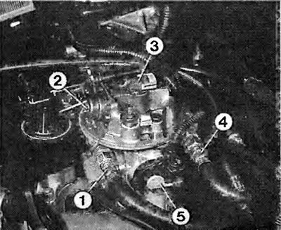
Units of the Multec central injection system. The numbers indicate:
1 - fuel recirculation hose;
2 - pressure regulator;
3 - injection valve;
4 - fuel supply hose;
5 - throttle potentiometer.
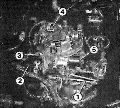
View of the Multec central injection system on the right side of the engine. Visible:
1 - throttle cable;
2 - coolant hose for heating the intake manifold;
3 - vacuum hose to the intake manifold pressure sensor;
4 - injection valve;
5 - stepper motor for supplying the working mixture at idle.
Engine speed limitation
When the maximum speed is exceeded, the control unit, protecting the engine, cuts off the fuel supply. Engine speed limitation in vehicles with a catalytic converter cannot be carried out by switching off the ignition, otherwise unburned fuel will enter the catalyst. This can lead to dangerous temperature peaks and damage to the catalytic converter.
Visitor comments