


Contents: Checking fuel pressure ⬇ Checking the injection valve ⬇ Checking the throttle potentiometer ⬇ Checking the stepper motor that…⬇ Checking the intake manifold…⬇ Checking the traction switch ⬇ Checking the coolant temperature…⬇ Checking the lambda adjustment ⬇ Replacing the lambda probe ⬇
The following sections describe tests of injection system components that are possible using amateur tools.
Checking fuel pressure
Fuel pressure can only be accurately measured with measuring equipment in a workshop.
- If you suspect incorrect fuel pressure, disassemble the pressure regulator.
- To do this, unscrew the four bolts with holes for a star key.
- Check if the diaphragm is damaged or if dirt has accumulated.
- When installing, make sure that the diaphragm is correctly positioned in the groove of the throttle body.
- Tighten the bolts to 2.5 Nm.
Checking the injection valve
- Check with the engine running: its oil temperature should be at least 60°C, which corresponds to a ten-minute drive after starting a cold engine.
- Remove the air intake pipe on the injection module.
- Start the engine and let it idle.
- Observe the injection valve jet. The jet it injects should be smooth and directed toward the throttle valve.
- Turn off the engine to check the valve for leaks.
- When the engine is not running, no more than 2 drops should flow per minute.
- The checks described below are only performed if the engine does not start.
- Remove the air intake pipe on the injection module.
- Have an assistant turn the engine over with the starter.
- The injection valve should inject fuel.
- If not, disconnect the connector on the injection valve.
- Connect an ohmmeter to both connecting contacts (to the injection module).
- At an air temperature of about 20°C the device should show 1.4-1.6 W.
- When the engine is hot, the resistance value rises to approximately 1.6-2.1 W.
- If these values are not obtained, the injection valve is faulty.
- When dismantling, unscrew the bolt with a hole for a star key and remove the bracket.
- Use a screwdriver to press the injection valve out of the housing.
- Use new sealing rings when installing. Lubricate the mounting bolt with safety compound and tighten to 3 Nm.
- The voltage supply to the injection valve is checked if the valve, despite the correct values, does not inject fuel.
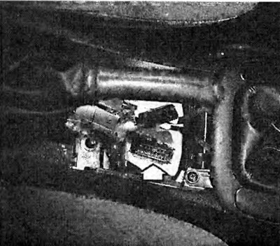
In our Vectra, the diagnostic socket (arrow) is located in the center console. The diagnostic socket is visible after removing the cover under the handbrake handle.
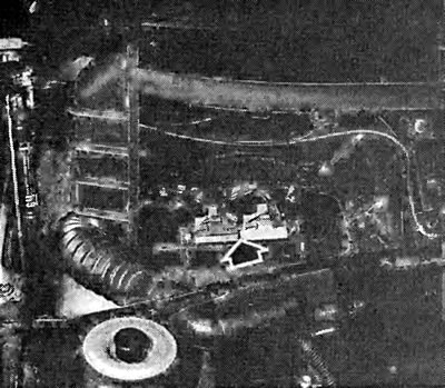
The photo shows the exposed ignition/injection control unit on the right side of the engine bay under the water deflector.
- Connect an LED indicator—do not use anything else—to both middle contacts in the disconnected connector.
- Operate the starter: the LEDs should light up, otherwise there is a conductivity problem in the wires or the control unit is faulty.
Checking the throttle potentiometer
The throttle valve potentiometers are manufactured by two different suppliers. They have the same appearance and function, but when testing the potentiometer, they give different resistance readings. The potentiometer of the manufacturer CTS has the inscription CTS in the rounding at the top left, the potentiometer NEI does not have such an inscription.
- The ignition is off.
- Disconnect the connector on the potentiometer.
- Connect an ohmmeter to terminals "A" and "B" on the potentiometer.
- Read the ohmmeter reading with the throttle valve closed. Potentiometer NEI -4.0-6.0 kW; potentiometer CTS - 4.0-9.0 kW.
- Connect an ohmmeter between terminals "B" and "C". Measurement result with NEI potentiometer: 3.0-4.0 kW and with CTS potentiometer: 1.0-3.0 kW.
- Now slowly open the throttle valve and read the ohmmeter readings with the valve fully open - NEI 6.0-7.0 kW potentiometer; potentiometer CTS 5.0-10.0 kW.
- If the specified values are not obtained, the throttle potentiometer is faulty
- The potentiometer is secured to the throttle body injection module housing with two star-head bolts.
- When installing a new potentiometer, tighten the bolts to 2 Nm.
[Original source is on the website: OpelBook.ru]
Checking the stepper motor that controls the supply of the working mixture at idle speed
- Disconnect the connector on the stepper motor.
- Set the battery charger to 6 volts and connect it alternately to terminals "A" and "B", then "C" and "D". You can hear the plunger moving in and out.
- If so, the idle fuel flow stepper motor is OK. If not, replace it.
- Those who do not believe the results obtained can check the winding resistance between terminals "A" and "B", "C" and "D". It should be equal to 50-65 W.
- If you are installing a new stepper motor, make sure that the distance between the end of the pusher and the housing flange does not exceed 28 mm. If necessary, gently push the pusher in.
- Insert the bolts with the safety mass and tighten to 3 Nm.
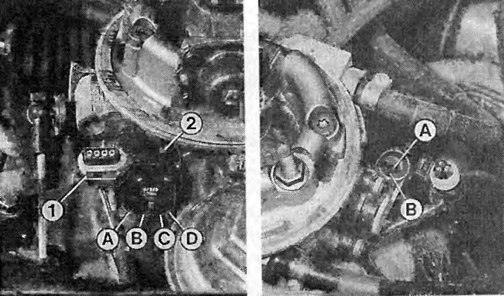
Left: Checking the stepper motor (2) that controls the supply of the combustible mixture at idle: disconnect the connector (1), switch the battery charger to 6 V and connect it alternately to terminals "A" and "B" or "C" and "D".
Right: To check the throttle potentiometer, an ohmmeter is connected to its terminals "A" and "B".
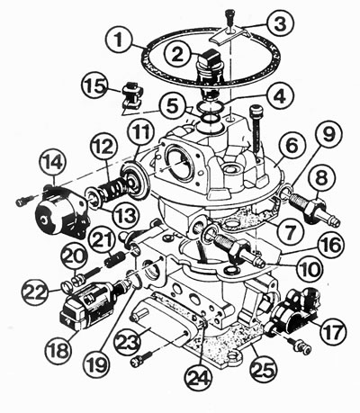
Multec central injection system components:
1 - air filter gasket;
2 - injection valve;
3 - injection valve bracket;
4, 5 - injection valve circular cross-section ring at the top or bottom;
6, 1 - upper part of the throttle valve injection housing with gasket;
8, 9 - fuel supply pipe with gasket;
10 - fuel return pipe;
11-14 - diaphragm, spring, spring seat and fuel pressure regulator cover;
15 - rubber tip of connecting wire;
16 - throttle valve part;
17 - throttle potentiometer;
18 - idle stepper motor;
19 - O-ring;
20-22 - idle speed adjusting screw with spring and cover (seal);
23, 24 - vacuum connection flange with gasket;
25 - injection module/intake manifold housing gasket.
Checking the intake manifold pressure gauge
To accurately check the manifold pressure gauge, the workshop uses a vacuum pump. A hobbyist can also perform a temporary check without a vacuum pump.
- Connect the voltmeter to the intake manifold pressure sensor by inserting the needle into the green wire (terminal B). Make sure that the needle does not touch bare metal (ground).
- Connect the positive terminal of the voltmeter to the needle. Attach the negative terminal to ground.
- Turn on the ignition. The voltmeter should show 4.2-5.3 V.
- Start the engine and let it idle. The voltmeter now shows 0.52-1.7 V.
- Increase the engine speed. The voltage value alternately rises and falls.
- If the readings are correct, the intake manifold pressure gauge is OK.
Checking the traction switch
- Remove the upper part of the air filter.
- Start the engine, increase the speed to 3000 rpm and close the throttle valve sharply.
- The clearly visible jet from the injection valve will be interrupted for a moment at this point. In this case, the traction shutdown is OK.
- If not, check the throttle potentiometer, manifold pressure sensor and control unit (in the workshop).
Checking the coolant temperature sensor
With the built-in thermometer you can check the correct operation of the temperature sensor. The sensor is located under the injection system in the intake manifold.

- Disconnect the wire connector on the temperature sensor and unscrew the sensor from the intake manifold. Collect the leaking coolant in a container.
- Hang the sensor in a pan of water, heat the water and connect an ohmmeter to the connector contacts.
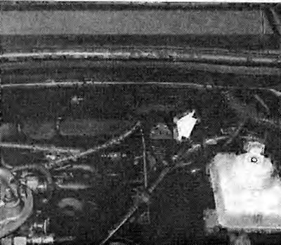
The photo shows the intake manifold pressure sensor on the right, next to the brake booster. Read about its purpose on page 77.
Check the corresponding resistance values at the temperatures indicated above.
If the values match, the temperature sensor is OK.
Checking the lambda adjustment
For this purpose, a voltmeter with a suitable lower measuring range, such as those owned by electronics enthusiasts, is used.
- Checking the voltage supply to the lambda probe: disconnect the lambda probe wire connector. The connector is located in the mount on the gearbox.
- Connect a voltmeter between the signal wire (brown/blue wire) and mass.
- Turn on the ignition. The measuring device should show 430-470 mV. If the device shows nothing, check the wire along its entire length to the control unit.
- Checking the lambda probe: connect the wire connector.
- Warm up the engine.
- Insert a needle into the probe signal wire. Connect a voltmeter between the needle and the ground. Make sure that the needle does not touch the ground (danger of short circuit).
- Let the engine run at approximately 1500 rpm.
- The measuring device should show short, rhythmic voltage fluctuations from 50 to 950 mV.
- No voltage fluctuations: the lambda probe is faulty (replace), the combustible mixture is constantly lean or rich (check the injection in the workshop) or the control unit is faulty (check in the workshop).
Tip: The main condition for a functioning lambda control is the correct basic setting of the idle speed, i.e. the CO content must be correct, otherwise the control will always be at the end of the control range. The same applies if the fuel-air mixture is greatly depleted due to secondary air.
Replacing the lambda probe
The probe thread is lubricated with a special anti-seize lubricant. It consists of liquid graphite, which burns during operation, and glass beads. The new probe is supplied with this lubricant, the thread of the old probe must be lubricated with this lubricant (Opel No.19 48 602).
- Warm up the engine. The lambda probe should only be removed when the engine is warm.
- Disconnect the lambda probe connector in the engine compartment. The connector is located in the mount on the gearbox.
- Unscrew the lambda probe from the exhaust manifold.
- Protect your hands from burns (work gloves, rag).
- When installing, tighten the probe to 30 Nm.
Visitor comments