


Fuel is sucked from the fuel tank by an electric pump and supplied through the fuel filter to the fuel distribution pipe, and from there to the injectors. The pressure regulator maintains the pressure in the fuel system at a level of 2.0±0.2 bar (ML4.1 and M1.5). An electrically controlled injector injects fuel into the intake manifold in front of the intake valve.
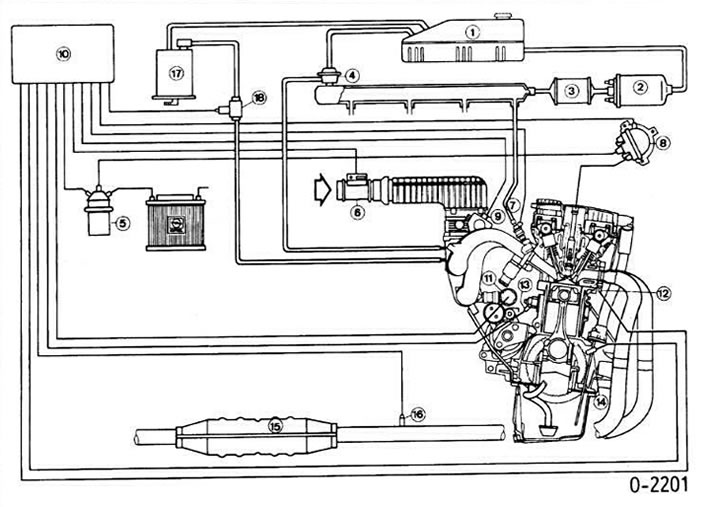
Motronic system diagram for 16-valve engine
1 - fuel tank
2 - fuel pump
3 - fuel filter
4 - fuel pressure regulator
5 - ignition coil
6 - air volume meter (8-valve engine - air flow meter)
7 - nozzle
8 - ignition distributor
9 - throttle position sensor
10 - computer
11 - idle speed controller
12 - coolant temperature sensor
13 - knock sensor (only for 16-valve engine)
14 - crankshaft position and speed sensor
15 - catalyst
16 - lambda probe
17 - activated carbon filter
Air is sucked in by the engine through the air filter, and its volume is measured by a special sensor. The sensor housing contains a special flap, which is deflected by the air flow and held in this position. The angle of the flap deflection allows us to judge the volume of air entering the engine. Information from the sensor connected to the flap is transmitted to the computer. The computer, based on information about the air volume and the engine speed, determines the injection moment and the amount of injected fuel. With a longer opening of the injector, the amount of incoming fuel increases.
In the Motronic ML4.1 system, the throttle position sensor is located on the valve axis. It controls the fuel supply. While the idle switch contact is closed and the engine speed is above a certain value, the fuel supply to the engine is switched off by the computer. In the Motronic M1.5 system, the throttle position information is transmitted to the computer by a sensor with a potentiometer.
The fuel pump relay is located in the engine block behind the left shock absorber strut. It controls the fuel pump. The switch interrupts the current supply as soon as the ignition pulses stop (for example, if the engine stalls).
The crankshaft position and speed sensor is located on the side of the cylinder block. It transmits information about the crankshaft speed to the computer.
Lambda probe (oxygen sensor) measures the residual oxygen content in the exhaust gases in the exhaust system with a controlled catalyst and transmits this information to the computer. Accordingly, the computer changes the ratio of "fuel/air" in the combustible mixture to obtain the required composition of the exhaust gases for the most effective operation of the catalyst.
The idle speed control valve regulates the amount of air at idle speed by acting on the throttle valve. Thanks to its operation, a stable idle speed is achieved regardless of whether additional loads such as power steering or air conditioning are turned on or off.
The injection system control computer is located in the footwell on the right behind the plastic trim.
Motronic system M2.5 16-valve engine
In this system, the air volume sensor operates on a different principle. This sensor has the following advantages: small dimensions, automatic compensation for the influence of ambient air temperature and altitude, no moving parts and, as a result, little wear. The main element of such a sensor is an electric coil blown by an air flow. To maintain a constant temperature of the coil, the amount of current needed to heat it changes in accordance with the change in air flow. Current fluctuations are signals for the computer about the engine load. Accordingly, the amount of fuel injected is regulated.
Fuel injection occurs sequentially, i.e. the injectors inject fuel in accordance with the order of cylinder firing. The optimum ratio of engine power and exhaust gas toxicity is achieved by determining the start time of injection in relation to the moment of opening of the intake valves.
The injection system has a knock sensor, with the help of which the ignition timing is set as early as possible (at the threshold of detonation). The computer also takes into account the octane number of the fuel used. The presence of a knock sensor allows you to increase the compression ratio (compression) in the engine cylinders. Thus, the energy of fuel combustion can be used to the maximum, which in turn leads to its savings. The knock sensor is installed on the cylinder block and is connected to the computer by wires. If the sensor fails, the computer automatically shifts the ignition timing to an earlier one, which eliminates the possibility of engine damage due to detonation. However, this leads to a decrease in engine power.
The fuel pressure in the injection system is approximately 3.0 bar.
Motronic M2.7 system in 2.0L turbocharged engines
The Motronic M2.7 system for Opel Calibra vehicles with a 2.0-liter turbocharged engine is a further development of the Motronic M2.5 system and is designed for more severe operating conditions.
In this system, instead of a throttle position sensor-switch, a potentiometer is used, mounted on its axis. With its help, the position of the valve is precisely determined.
To determine the temperature of the intake air, a temperature sensor is installed in the pipe where the throttle valve is installed.
The turbo boost pressure is controlled by the computer via the turbocharger electromagnetic valve. There is a built-in sensor to measure the pressure in the valve. In addition, two switches are installed in the gearbox, which are also connected to the injection system computer. When 1st gear or reverse gear is engaged, they send a signal to the computer, which reduces the boost pressure and thereby reduces the torque.
Attention! When working with the injection system, it is necessary to maintain exceptional cleanliness. Before disassembling the system, its elements must be washed.
Attention! The system is under pressure. When replacing any of its elements, the pressure must be released. To do this, carefully loosen the pipeline fastenings between the fuel pump and the filter. If the pipeline is disconnected, close its end with the appropriate plug. The pressure drops by itself (without disconnecting the pipeline), if the engine has not been running for several hours.
Visitor comments