


At the moment when the piston is almost at the top dead center, diesel fuel is injected into the air, compressed and heated to +700-900°C. The fuel is self-igniting, so spark plugs are not needed.
When the engine is very cold, the ignition temperature cannot be reached by compression alone.
In this case, the engine must be pre-warmed. For this purpose, each combustion chamber has a glow plug that heats the combustion chamber. The warm-up duration depends on the ambient temperature and is regulated by the engine control unit via the warm-up relay.
To reduce the content of harmful substances in exhaust gases, diesel engines are equipped with a special diesel catalytic converter. At the same time, the recirculation system ensures a further reduction in the amount of nitrogen compounds in the exhaust gases.
A similar effect is achieved by mixing gases and fresh air. At the same time, the oxygen content in the exhaust gases decreases.
The volume of exhaust gases returned for afterburning must be dosed, because their uncontrolled flow leads to the formation of carbon deposits and an increase in the content of solid particles in the exhaust gases. Therefore, the air volume is controlled by a flow meter (mass air flow meter), and the exhaust gas recirculation system is controlled by a microprocessor.
The diesel engine control unit recognizes faults and malfunctions in the fuel system and records them, creating an error log, where faults are recorded as codes.
In the workshop, using a tester connected to the diagnostic connector, the error log is opened and the registered faults can be specifically eliminated without wasting time and effort searching for them.
Diesel engines use two different fuel injection methods: swirl or pre-chamber injection and direct injection (direct) injection.
The diesel-powered vehicles in question use only direct injection, i.e. fuel is injected directly into the combustion chamber via a high-pressure fuel pump (HPFP).
Fuel is supplied to the high-pressure fuel pump by a fuel supply pump, which allows the high-pressure fuel pump to create a sufficiently high pressure for fuel injection even at low engine crankshaft speeds.
From the high-pressure fuel pump, fuel enters the so-called distribution (fuel) rail, and from there - to the injectors of the corresponding cylinders. The distribution (fuel) rail serves as a fuel tank in which constant pressure is maintained.
The intake ports are designed in such a way that they impart a strong swirl to the air, which, together with the shape of the combustion chamber, creates strong turbulence during the compression stroke.
The engine control unit controls the fuel injection timing via the injection advance control valve on the fuel pump. The amount of fuel injected by the pump depends on the engine crankshaft speed and boost air pressure.
The required volume of injected fuel is determined and set by a microprocessor, which regulates the duration of the injector opening.
The absence of a pre-chamber reduces the heat exchange area, so the engine burns less fuel to heat the coolant, thereby improving its efficiency.
With only one chamber, combustion occurs in one stage, which ensures high power and minimal emissions.
The accelerator pedal position sensor is located on the pedal shaft. The sensor potentiometer transmits information about the pedal position to the engine control unit.
The high-pressure fuel pump does not require maintenance. All rubbing parts of the pump are lubricated with diesel fuel. The fuel injection pump is driven by a chain from the crankshaft.
Before entering the injection pump, the fuel passes through a fuel filter. Dirt and water are trapped in the filter, so it is extremely important to replace the fuel filter or remove water from it.
The engine control unit controls the fuel injection timing via the injection advance control valve on the fuel pump. The amount of fuel injected by the pump depends on the engine crankshaft speed and boost air pressure.
The required volume of injected fuel is determined and set by a microprocessor, which regulates the duration of the injector opening.
The crankshaft angle sensor transmits signals to the engine control unit that allow the correct determination of the fuel injection moment.
The boost air pressure sensor measures the pressure in the intake manifold. Based on its signals, the electronic engine control unit limits fuel injection if the boost pressure regulator fails.
The exhaust gas recirculation valve directs, depending on the engine load, a certain amount of exhaust gases for afterburning, mixing them with the intake air.
The diesel engines in question are equipped with a turbocharger. In a turbocharger, two turbine wheels are installed on one shaft, which are located in housings separated from each other.
The turbine wheels are driven by exhaust gases, which bring the supercharger shaft speed to 120,000 min⁻¹, and since the exhaust and fresh air rotors are located on the same shaft, air is forced into the cylinders at the same speed.
Due to the good filling factor in existing engines, power gains of up to 100% can be achieved.
Along with the increase in engine power, the use of a turbocharger also increases torque, which is especially important in terms of achieving good elasticity of engine running.
In contrast to the internal combustion engine, the diesel engine does not need to reduce compression due to air supercharging, which ensures full use of fuel energy even at low engine crankshaft speeds.
The turbocharger is an extremely precisely manufactured unit, so in case of repair it is recommended to contact only a specialist. As a rule, in case of a malfunction, the turbocharger is replaced completely.
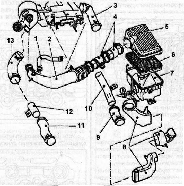
Air filter and air ducts: 1 - crankcase ventilation hose; 2 - air duct connecting the air flow meter and turbocharger; 3 - air duct connecting the intake manifold and the intercooler of the supercharged air; 4 - air flow meter; 5 - air filter cover; 6 - air filter element; 7 - air filter housing; 8 - air intake pipe; 9 - air duct connecting the intercooler of the supercharged air and the intake manifold; 10 - air duct connecting the intercooler of the supercharged air and the turbocharger; 11 - air duct connecting the turbocharger and the intercooler of the supercharged air; 12 - air duct connecting the turbocharger and the intercooler of the supercharged air; 13 - air duct connecting the turbocharger and the intercooler of the supercharged air
Visitor comments