
2. Remove the release bearing and lever as described in Section 5.
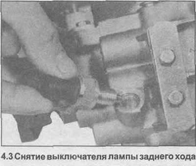
3. Unscrew and remove the reversing lamp switch (photo).
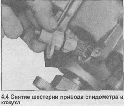
4. Turn off a bolt, get a gear wheel of a drive of a speedometer and a casing (photo).
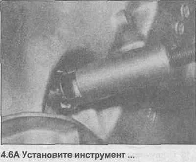
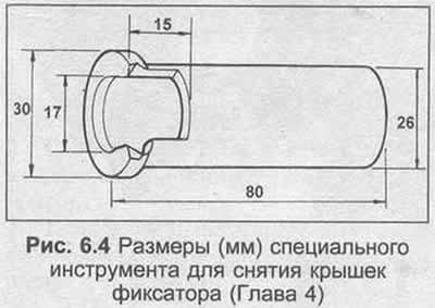
5. Now you need to remove the pin of the gear lever shaft retainer, which is attached with a special cover. The GM tool for this operation is KM-630-1 and is used in conjunction with a hammer. If it is not possible to use this tool, a substitute can be made according to the dimensions shown in Fig. 6.4. The grip must be welded, soldering will not be strong enough.
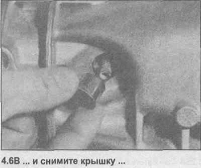
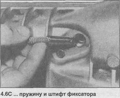
6. Use a cover removal tool, then remove the spring and detent pin (photo).
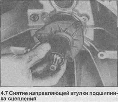
7. Inside the clutch housing, unscrew the bolts and remove the clutch bearing guide bushing above the input shaft (photo).
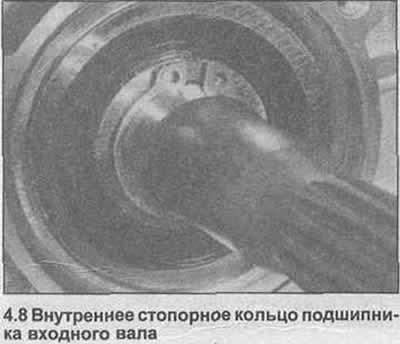
8. Use pliers to remove the inner retaining ring that secures the input shaft bearing (photo).
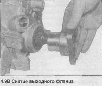
9. Secure the outlet flange by bolting a piece of metal rod to it, then unscrew the flange nut using a 32.0mm socket. Remove the flange with a suitable extractor (photo).

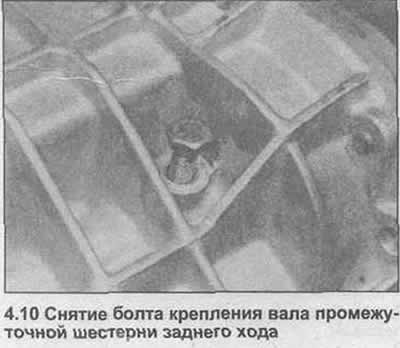
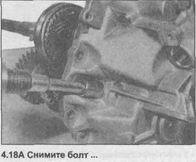
10. Loosen and remove the reverse idle gear shaft bolt (photo).
11. Remove the bolts securing the rear support housing to the main casing.
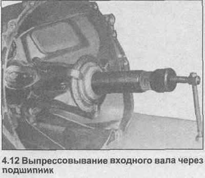
12. The input shaft should now be pressed through the bearing in the main housing to expose the rear support housing and gear. A suitable tripod puller can be used by bolting the legs to the main housing (photo).
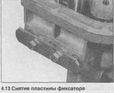
13. Unscrew the bolts and remove the retainer plate from the rear support housing (photo).
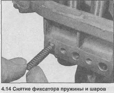
14. Remove the detent springs, then the detent balls (photo).
15. Using a thin bit, push the roll pins out of the shift forks while supporting the shafts with a bar.
16. Note the position of the gear forks and shafts, make marks if necessary.
17. Pull out the rollers of the leash, disconnect the gear shift forks from the synchronizer bushings. Rotate the shift lever shaft as needed to move the selector pin out of the way.
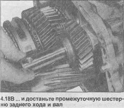
18. Remove the reverse idle gear shaft bolt. Pull out the shaft until the reverse idler gear comes out (photo). Remove needle bearings.
19. Squeeze together the retaining ring that secures the output shaft bearing to the rear support housing, lock it in the compressed position using a bent piece of metal rod (photo).

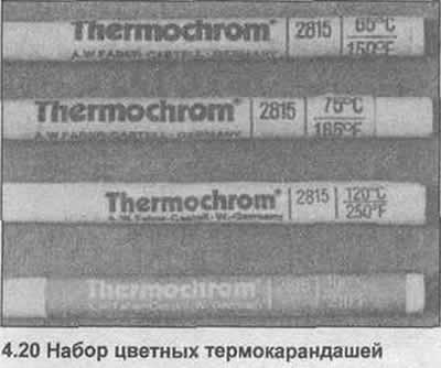
20. The housing should now be heated to 100°C to remove the output shaft bearing and gear. It is recommended to use colored thermal pencils (photo), to maintain the correct temperature.
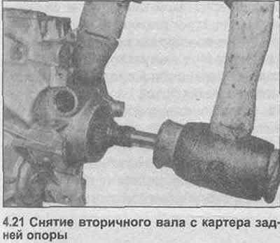
21. When the desired temperature is reached, carefully knock out the secondary shaft from the housing and remove the gearbox as an assembly (photo).
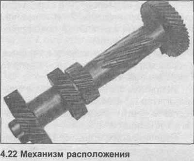
22. Separate the location mechanism from the input shaft and output shaft (photo).
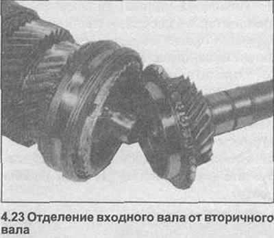
23. Separate the input shaft from the output shaft (photo).
Visitor comments