
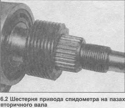
2. Pull the speedometer drive gears off the back of the output shaft (photo).
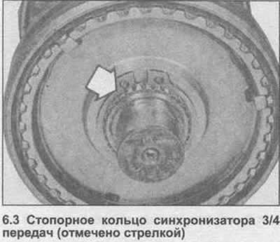
3. Using pliers, remove the retaining ring from the front end of the output shaft (photo).
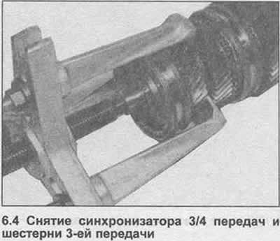
4. Using an extractor, remove the 3/4 synchro and 3rd gear (photo). Also remove the 3rd gear needle bearing.
5. Separate the 3rd/4th gear synchronizer from the 3rd gear and remove the 3rd gear synchronizer ring. Mark the position of the synchronizer ring.
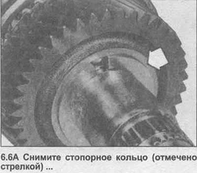
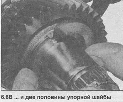
6. Remove the st support ring, then release the two halves of the thrust washer (photo).
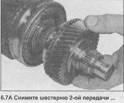
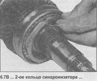
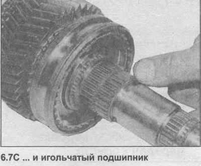
7. Remove the 2nd gear and 2nd gear synchronizer ring. Also remove the 2nd gear needle bearing (photo).
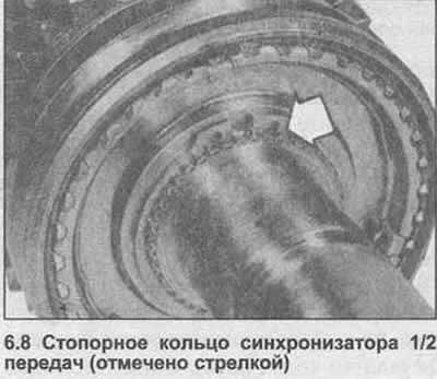
8. Use pliers to remove the retaining ring securing the 1/2 gear synchronizer (photo).
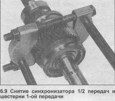
9. Using an extractor, remove the 1/2 gear synchronizer and 1st gear (photo). Also remove the needle bearing.
10. Separate the 1/2 gear synchronizer from the 1st gear and remove the 1st gear synchronizer ring. Mark the position of the ring.
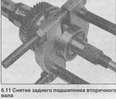
11. Using an extractor, remove the ball bearing from the back of the output shaft (photo).
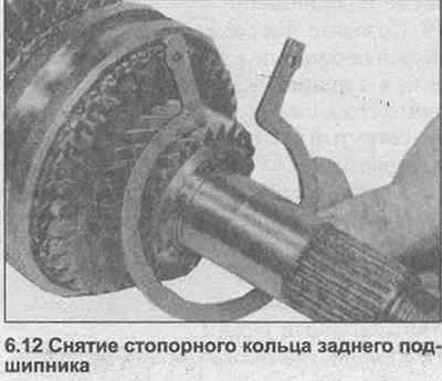
12. Remove the bearing circlip (photo).
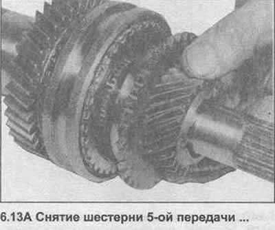
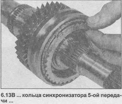
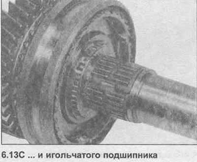
13. Remove the 5th gear, 5th gear synchronizer ring and needle bearing (photo).
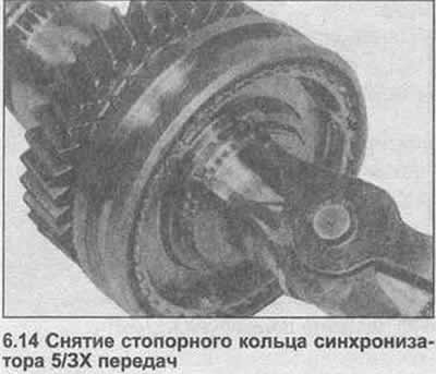
14. Using pliers, remove the retaining ring securing the 5/3X gear synchronizer (photo).
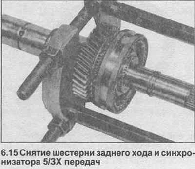
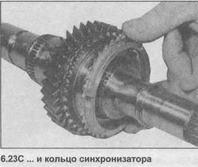
15. Using an extractor, remove the reverse gear along with the 5/3X gear synchronizer from the rear of the output shaft (photo). Separate the gear from the synchronizer and remove the reverse synchronizer ring.
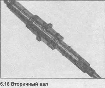
16. Remove the roller bearing from the secondary shaft (photo).
17. If necessary, synchronizers can be disassembled as follows.
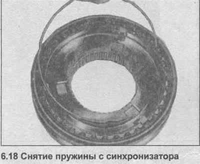
18. Remove the springs from each side of the synchronizer (photo).
19. Mark the synchronizer hub and sleeve relative to each other, then pull the sleeve and remove the sliding keys.
20. Clean all components, inspect for wear and damage, replace as needed.
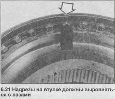
21. Assembly begins with synchronizers as follows. Pull the sleeve onto the hub, aligning the previously made marks. The notches in the bushing must match the slots in the sliding key on the same side (photo).
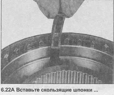
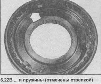
22. Insert the sliding keys into the slots, then install the springs (photo). Note that the spring for the 4th synchronizer ring is approximately 10.0 mm longer.
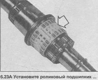
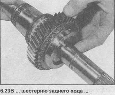
23. Place the reverse gear roller bearing on the output shaft, then the reverse gear and the reverse synchronizer ring (photo).
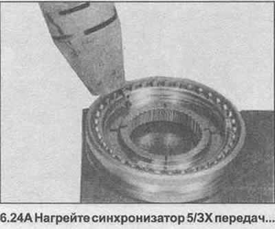
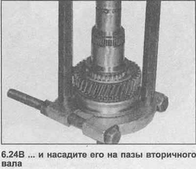
24. Heat the 5/3X gear synchronizer to approximately 100°C. Push the synchronizer onto the grooves of the output shaft immediately with the extractor, making sure that the sliding keys fit into the grooves in the synchronizer ring (photo).
25. Install the retaining ring in the groove.
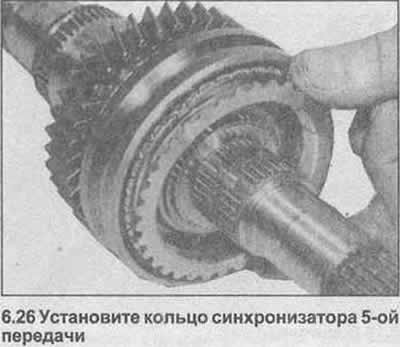
26. Install the 5th gear needle bearing, 5th synchronizer ring and 5th gear (photo). Make sure that the sliding keys fit into the grooves of the synchronizer ring.
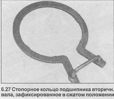
27. Position the bearing circlip over the 5th gear. Alternatively, the circlip can be secured in the compressed position with a piece of wire (photo).
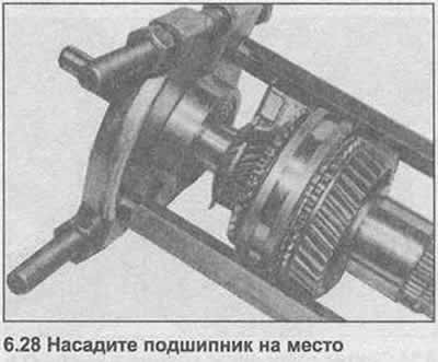
28. Using an extractor, fit the bearing onto the output shaft with the closed side towards the gear (photo).
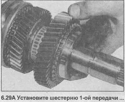
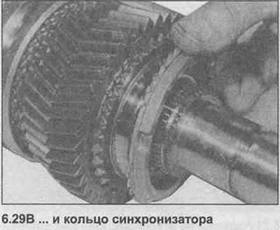
29. Install the 1st gear needle bearing, then the 1st gear and the 1st gear synchronizer ring (photo).
30. Heat the 1/2 gear synchronizer to approximately 100°C. Push the synchronizer onto the grooves of the mainshaft immediately using an extractor, making sure that the sliding keys fit into the grooves in the synchronizer ring. The identification groove on the bushing must face the front end of the output shaft (photo).

31. Install the retaining ring in the groove.
32. Install the 2nd gear needle bearing, then the synchronizer ring and 2nd gear. Make sure the sliding keys fit into the slots in the synchronizer ring.
33. Install the two halves of the thrust washer, secure them with a ring.
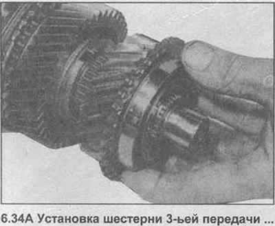
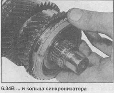
34. Install the 3rd gear needle bearing, then the 3rd gear and synchronizer ring (photo).
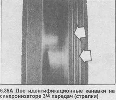
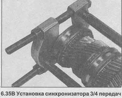
35. Heat the 3/4 gear synchronizer to approximately 100°C. Push the synchronizer onto the output shaft grooves immediately using an extractor. Make sure the sliding keys fit into the slots in the synchronizer ring. The identification grooves on the bushing must face the front end of the output shaft (photo).
36. Install the retaining ring in the groove.
37. Place the 4th synchro ring into the 3/4 synchro.
38. Push the speedometer drive onto the back of the output shaft.
Visitor comments