OpelBook.ru
Cars AvtoVAZ Cars Mitsubishi Cars BMW Cars Mercedes Cars Nissan Cars Toyota Cars Chevrolet
English Русский
Български
Беларускі
Український
Српски
Hrvatski
Română
Polski
Slovenský
Magyar
 |  Sitemap  |  Contacts  |    


Main Astra Corsa Insignia Kadett Omega Vectra Zafira Others Articles
Omega A (1986-1993) Omega B (1993-1999) Omega B2 (1999-2003)
  • Main
  • Omega
  • Omega A
  • Transmission
  • Mechanical gearbox
  • Manual gearbox — assembly

Manual gearbox — assembly (Opel Omega A)

            0

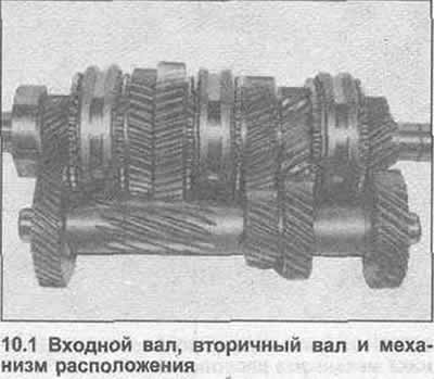
1. Assemble the input and secondary shafts, then fold the positioning mechanism with them (photo).

1. Assemble the input and secondary shafts, then fold the positioning mechanism with them (photo).


2. Clamp the rear crankcase in a vice, heat the housing around the bearing seat to approximately 100°C.

3. Lower the gearbox into the housing, making sure that the secondary shaft bearing is fully seated (photo).
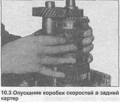
3. Lower the gearbox into the housing, making sure that the secondary shaft bearing is fully seated…


4. Place the snap ring in the groove, remove the piece of wire.

5. Place the output flange on the secondary shaft slots, screw on the nut. Fix the flange and tighten the nut with the tightening torque specified Specification (photo).
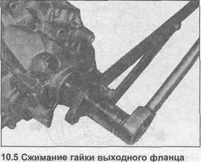
5. Place the output flange on the secondary shaft slots, screw on the nut. Fix the flange and…


6. Place the needle bearings in the reverse idler gear, place the gear on the housing, insert the shaft. Note that the identification groove on the mechanism should be facing forward (photo).
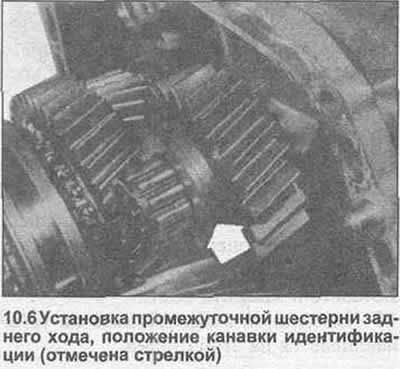


6. Place the needle bearings in the reverse idler gear, place the gear on the housing, insert the…


7. Insert and tighten the reverse intermediate shaft bolt.

8. Lubricate the two locking pins and insert them between the holes in the leash roller (photo).
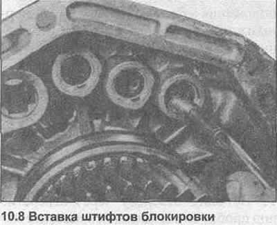
8. Lubricate the two locking pins and insert them between the holes in the leash roller (photo).


9. Insert the 5/3X gear engagement fork into the groove in the 5/3X gear synchronizer sleeve (photo).
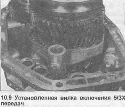
9. Insert the 5/3X gear engagement fork into the groove in the 5/3X gear synchronizer sleeve…


10. Check that all synchronizer bushings are in neutral position.


11. Insert the 1/2 gear selector fork into the groove in the 1/2 gear synchronizer sleeve. Insert the 1/2 gear carrier shaft through the fork into the rear case, then place the selector clamp on the shaft (photo).
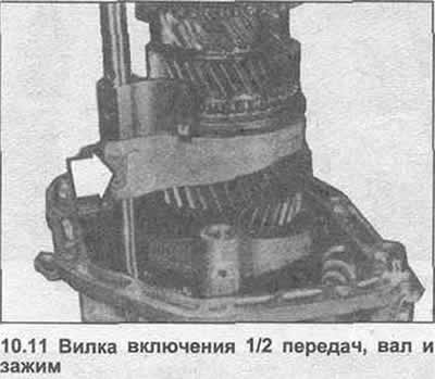
11. Insert the 1/2 gear selector fork into the groove in the 1/2 gear synchronizer sleeve. Insert…


12. Insert the 3/4 gear shift fork into the groove in the 3/4 gear synchronizer sleeve. Insert the 3/4 gear shifter shaft through the fork into the rear case and turn until the shifter fingers align (photo).
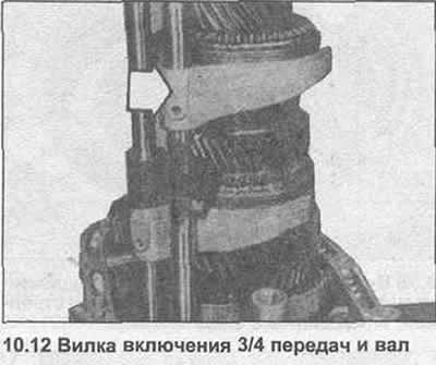
12. Insert the 3/4 gear shift fork into the groove in the 3/4 gear synchronizer sleeve. Insert the…


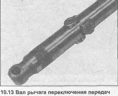
13. Lubricate the four rollers and place them on the pins on the gear shift lever shaft (photo).

13. Lubricate the four rollers and place them on the pins on the gear shift lever shaft (photo).

14. Insert the gearshift lever shaft with the selector pin into the rocker arm. Use a screwdriver to turn the rocker arm as needed to help the shaft enter and to allow the selector pin to enter the switches (photo).
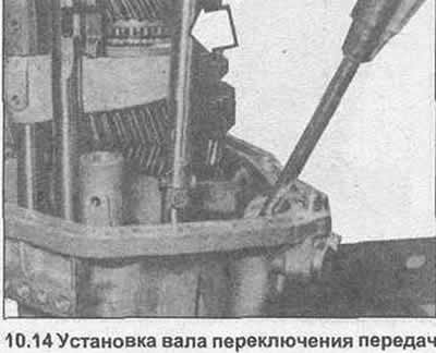


14. Insert the gearshift lever shaft with the selector pin into the rocker arm. Use a screwdriver…


15. Insert the 5/3X gear shift shaft through the 5/3X gear engagement fork into the rear housing (photo).
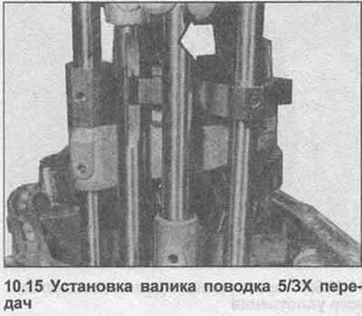
15. Insert the 5/3X gear shift shaft through the 5/3X gear engagement fork into the rear housing…


16. On each leash roller, align the holes, hammer in the cylindrical pins until they protrude outward by approximately 1.0 mm (photo).
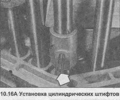
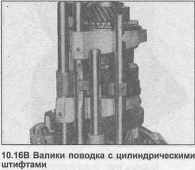
16. On each leash roller, align the holes, hammer in the cylindrical pins until they protrude…


16. On each leash roller, align the holes, hammer in the cylindrical pins until they protrude…


17. Insert the ball retainers and springs into the rear housing.


18. Apply sealant to the retainer plate (photo), then install it on the springs, insert the bolts and tighten them to the tightening torque specified in the Specification.
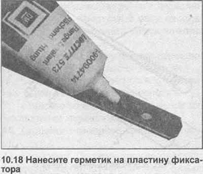
18. Apply sealant to the retainer plate (photo), then install it on the springs, insert the bolts…


19. Engage 4th gear and check that the remaining synchronizer rings are not clamped on their respective gear cones. If necessary, loosen the rings with a screwdriver.

20. Apply sealant to the rear case mating surface (photo).
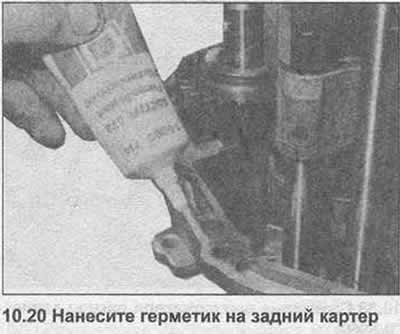
20. Apply sealant to the rear case mating surface (photo).


21. Carefully lower the main housing onto the rear crankcase, making sure that the driver rollers and positioning mechanism enter their corresponding holes (photo).
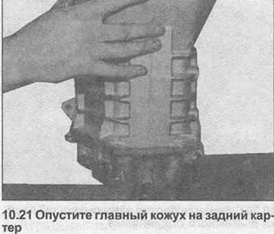
21. Carefully lower the main housing onto the rear crankcase, making sure that the driver rollers…


22. To install the input shaft bearing, prepare a special tool. It is not permissible to simply hammer the bearing into place, this can damage the synchronizer rings. It is also impossible to install the bearing retaining ring. GM tool #KM-461 (photo). It is made from a cut metal tube to provide a clamp to grip the input shaft. Two side bolts are used to press the bearing into the housing, using metal blocks to prevent damage to the bearing.
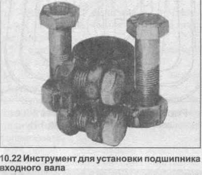


22. To install the input shaft bearing, prepare a special tool. It is not permissible to simply…


23. Before installing the bearing, heat the housing around the bearing seat to approximately 100°C.

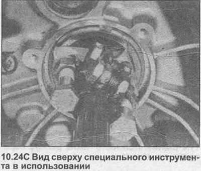
24. Place the bearing (with retaining ring) above the input shaft, using a special tool, insert it into the housing (photo). Check that the internal groove of the retaining ring is visible on the input shaft.
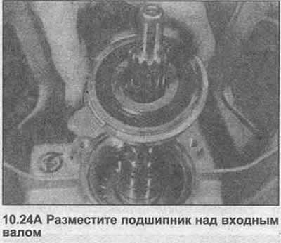
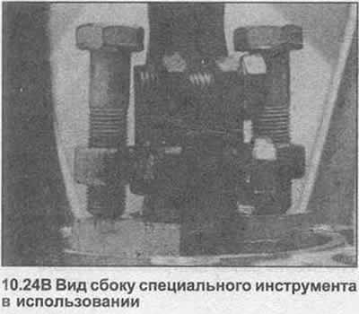
24. Place the bearing (with retaining ring) above the input shaft, using a special tool, insert it…


24. Place the bearing (with retaining ring) above the input shaft, using a special tool, insert it…


24. Place the bearing (with retaining ring) above the input shaft, using a special tool, insert it…


25. Remove the tool, then install the inner snap ring onto the input shaft.


26. Shift into neutral. Rotate the input shaft to ensure that the synchronizer rings are not pinched on their cones.

27. Insert the housing bolts, tighten them evenly with the specified tightening torque Specification (photo).

27. Insert the housing bolts, tighten them evenly with the specified tightening torque…


28. Insert the front bolt securing the reverse intermediate gear shaft and tighten it to the specified tightening torque Specification.

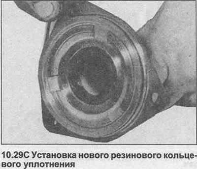
29. Remove the rubber O-ring from the clutch bearing guide sleeve. Clean the bearing surface, drive in a new seal using a metal tube or socket of the appropriate size. The closed side of the seal should be inside the sleeve. Install a new rubber O-ring (photo).
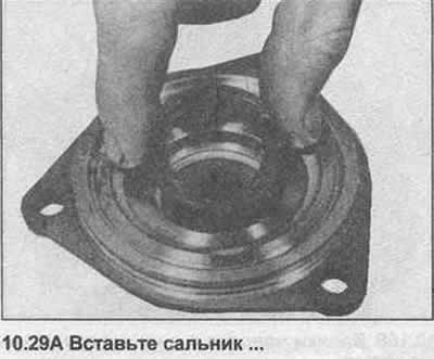
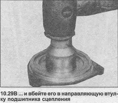
29. Remove the rubber O-ring from the clutch bearing guide sleeve. Clean the bearing surface, drive…


29. Remove the rubber O-ring from the clutch bearing guide sleeve. Clean the bearing surface, drive…


29. Remove the rubber O-ring from the clutch bearing guide sleeve. Clean the bearing surface, drive…


30. Lubricate the seal lip, then install the clutch release bearing guide sleeve, being careful not to damage it on the input shaft grooves. Insert the bolts, tighten them to the specified tightening torque Specification (photo).
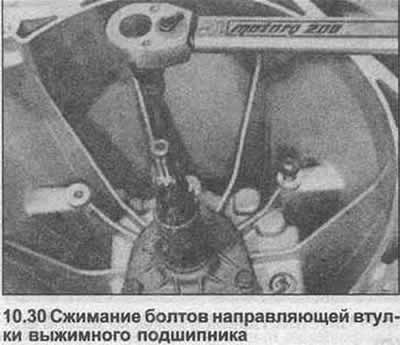


30. Lubricate the seal lip, then install the clutch release bearing guide sleeve, being careful not…


31. Insert the gearshift shaft retainer pin and spring, making sure the pin roller is horizontal. Tap the cover into the housing with a mallet.

32. Install the speedometer drive gear and housing. Insert and tighten the bolt.

33. Insert and press the reverse light switch (photo).
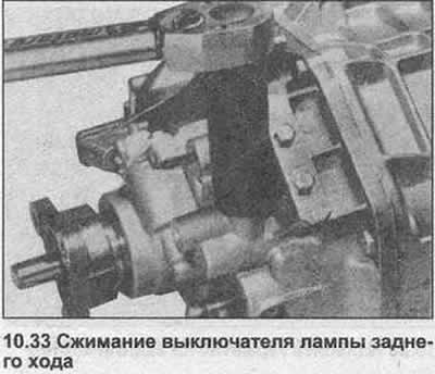
33. Insert and press the reverse light switch (photo).


34. Install the release bearing and lever as described in Section 5.


This article is available at russian, bulgarian, belarusian, ukrainian, serbian, croatian, romanian, polish, slovak, hungarian
Checking the article: Zinoviev Kirill

Share information:

Previous articles
Opel Omega A: Mechanical gearbox
Next articles

Main casing of manual transmission — disassembly and assembly
Rear housing of a manual transmission — disassembly and assembly
Input shaft of a manual transmission — disassembly and assembly
Secondary shaft of a manual gearbox — disassembly and assembly
Manual transmission — inspection
Manual gearbox — disassembly into main blocks
Manual transmission shift lever — removal, overhaul and installation
Gear Shift Lever Mounting Hanger — Removal and Installation
Gear shift rod for manual transmission — adjustment


See similar ones from other Opel car manuals:
▶ Manual gearbox — repair, general information Opel Astra F (1991-1998, petrol)
▶ Replacing transmission oil in a manual gearbox M32-6 Opel Insignia A (2008-2017)
▶ Malfunctions of a manual gearbox Opel Vectra C (2002-2008)
▶ Manual gearbox — technical condition check Opel Zafira A (1999-2005, petrol)
▶ Engine — installation (with manual gearbox) Opel Ascona C (1981-1988)
Link to this page in different formats

Visitor comments


No comments yet


How much will 38 + 37 =


Omega B2 (1999-2003) 
  • General information
  • User manual
  • Maintenance
  • Troubleshooting
  • Power unit
  • Petrol 4-cylinder
  • Petrol 6-cylinder
  • Engine overhaul
  • Diesel engines 2.0 l
  • Diesel engines 2.5 l
  • Cooling and heating
  • Injection system (gasoline)
  • Fuel system (diesel)
  • Fuel system
  • Exhaust system
  • Ignition system
  • Transmission
  • Clutch
  • Mechanical gearbox
  • Automatic gearbox
  • Main gear and shafts
  • Chassis
  • Brake system
  • Car suspension
  • Steering
  • Body
  • Body elements
  • Electrical equipment
  • Equipment and devices
  • Electrical circuits
Omega B (1993-1999) 
  • General information
  • User manual
  • Tips for the car owner
  • Maintenance (gasoline)
  • Maintenance (diesel)
  • Power unit
  • Petrol engine SOHC 2.0 l
  • Petrol engine DOHC 2.0 l
  • Petrol engines 2.5 and 3.0 l
  • Repair of gasoline engines
  • Diesel engine 2.0 l
  • Diesel engine repair 2.0 l
  • Diesel engine 2.5 l
  • Cooling and heating
  • Power system (petrol)
  • Emission reduction
  • Fuel system (diesel 2.0 l)
  • Fuel system (diesel 2.5 l)
  • Launch system
  • Ignition system
  • Transmission
  • Clutch
  • Mechanical gearbox
  • Automatic gearbox
  • Drive shafts
  • Chassis
  • Brake system
  • Wheel suspension
  • Steering
  • Body
  • Exterior
  • Interior
  • Doors and windows
  • Electrical equipment
  • Equipment and devices
  • Wiring diagrams (early)
  • Wiring diagrams (late)
Omega A (1986-1993) 
  • General information
  • User manual
  • Maintenance
  • Changes and additions
  • Troubleshooting
  • Power unit
  • Gasoline engines
  • Diesel engines
  • Cooling system
  • Fuel system (gasoline)
  • Fuel system (diesel)
  • Ignition system
  • Transmission
  • Clutch
  • Mechanical gearbox
  • Automatic gearbox
  • Cardan shaft
  • Drive shafts
  • Chassis
  • Brake system
  • Car suspension
  • Steering
  • Body
  • Exterior
  • Interior
  • Electrical equipment
  • Power devices
  • Lighting and appliances
  • Electrical circuits
OpelBook.ru © 2017–2026 · Mobile version · · Sitemap: EN BG BY UA RS HR RO PL SK HU · Feedback · Site search
Astra F, petrol · Astra G, petrol · Astra G · Astra H · Astra J, petrol · Corsa B · Corsa C, petrol · Corsa C · Insignia A · Kadett D · Kadett E · Omega A · Omega B · Omega B2 · Vectra A, petrol · Vectra A · Vectra B, petrol · Vectra B · Vectra C · Zafira A, petrol · Frontera A, petrol · Frontera B · Ascona C · Vivaro A ·
We want your visit to be comfortable 🤝! We use cookies 🍪 to make that happen.