


Warning: Brake fluid used as a working fluid in the clutch drive path is toxic and chemically aggressive and destroys the paintwork when in contact with body panels. Before starting the procedure, cover the fenders and front panel of the car with special covers or just old blankets. Bleed the brake system wearing safety glasses. If brake fluid accidentally gets into your eyes, rinse them immediately with plenty of water and seek medical help!
Caution: Even the slightest amount of mineral oil in the brake fluid will cause the clutch to fail!
1. The hydraulic clutch release drive must be bled each time its components are removed, and also when the fluid level in the reservoir drops so much that air gets into the master cylinder. When bleeding, use only fresh brake fluid of the required grade (DOT-4). Make sure that the union connections of the clutch hydraulic circuit are tight.
Attention: Do not reuse liquid that has been pumped out of the system, or liquid that has been stored for a long time in a loosely closed container!
2. Bleeding of the hydraulic circuit is performed through a special connection using a set of special equipment that is used for bleeding the working brake system.
Attention: Manual bleeding of the drive is not allowed on models equipped with ABS!
The general connection diagram of the kit is shown in the accompanying illustration - before using the kit, carefully read the operating instructions. The bleeding equipment must withstand an internal pressure of at least 2 bar.
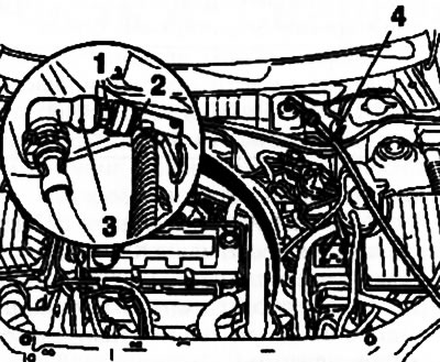
4.2. Connecting the clutch bleeding kit: 1. Bleed nipple; 2. Device MKM-6174-1; 3. Hydraulic line coupling unit; 4. Device MKM-6174-2
3. On models equipped with manual transmission F13/F17(ecex modifications)/F23 Remove the master cylinder reservoir cap and fill the reservoir with fresh hydraulic fluid, bringing its level to the MAX mark. Connect a special adapter to the reservoir and attach the MKM-6174-2 device to it (see illustration 4.2) - lower the free end of the hose into a suitable drain container. Remove the protective cap of the bleed nipple and connect the MKM-6174-1 device to it. Connect the other end of the device to the bleed device.
4. Turn on the pumping device, unscrew the nipple (see illustration 4.2) 2-3 turns, this will open the bleeding valve. Continue bleeding until air bubbles stop coming out of the drain hose. Manually tighten the coupling, turn off the bleeding device and remove the adapter from the brake fluid reservoir.
5. If necessary, bleed the hydraulic line between the coupling unit and the clutch slave cylinder by connecting the MKM-6174-2 device to the MKM-6174-1 and lowering the free end of the hose into a drain container with brake fluid. Ask an assistant to fully depress the clutch pedal and hold it pressed. After unscrewing the nipple, open the bleed valve and wait until air/air bubbles come out of the tract. Manually tighten the coupling, and pull out and set the clutch pedal to the normal position. Wait about 5 seconds. Repeat the above operation 4 more times.
6. On models equipped with an Easytronic robotic gearbox, the device should only be used in conjunction with the TESN-2 diagnostic device - read the device's instructions carefully. The adapter of the device MKM-6174-2 is installed on a separate reservoir of clutch fluid, fixed to the gearbox housing. On models equipped with the Z13DT engine, first remove the inflating nozzle.
Caution: Even the slightest amount of mineral oil entering the Easytronic brake fluid will cause the clutch to fail!
7. After completing the procedure, tighten the coupling to 5 Nm and remove all installed components.
(Article posted on a web portal: www.OpelBook.ru)
8. Remove traces of brake fluid leaks. Check the proper functioning of the clutch drive, as well as all drive components for leaks. If necessary, adjust the brake fluid level in the reservoir (see Chapter 1). The brake fluid level in the Easytronic system reservoir should also be between the "MIN" and "MAX" marks (see accompanying illustration).
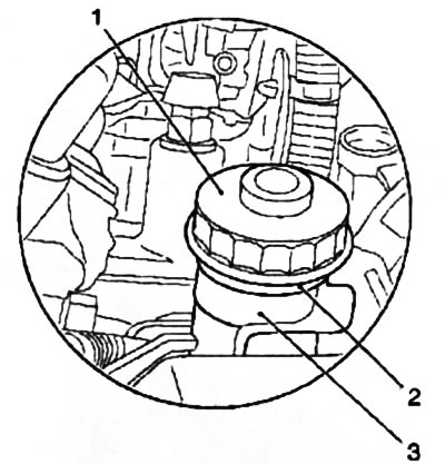
4.8. Checking the Easytronic clutch hydraulic fluid level: 1. Reservoir cap; 2. Mark "MAX"; 3. Mark "MIN"
Visitor comments