


2. The clutch is released hydraulically. The release drive consists of a clutch pedal, a main hydraulic cylinder with a reservoir, connecting lines and a slave cylinder combined with a release bearing, mounted directly on the input shaft of the gearbox (see illustration 1.1). Note: The reservoir is common for the clutch and service brake system drives.
3. Models with Easytronic have special drive and layout features. The clutch of these models is equipped with a control module (see accompanying illustration) and a separate reservoir for hydraulic fluid.
4. When the corresponding pedal is depressed, the hydraulic pressure in the system tract rises, which is then applied to the release bearing mounted in the slave cylinder. The bearing, under the influence of the hydraulic force, is pressed against the petals of the diaphragm spring of the pressure plate in the clutch basket. By bending, the spring interrupts the contact of the pressure and driven disks, releasing the latter.
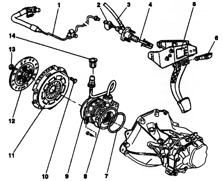
1.1. Design of the clutch and its drive components: 1. Clutch release drive hydraulic line; 2. Damper; 3. Hose connecting the master cylinder to the reservoir; 4. Clutch master cylinder push rod; 5. Clutch pedal bracket; 6. Clutch pedal position sensor switch (models with tempostat); 7. Sealing ring; 8. Assembling the clutch slave cylinder with release bearing; 9. Hydraulic line; 10. Clutch basket mounting bolt; 11. Assembling the clutch basket with the pressure plate; 12. Slave (friction) clutch disc; 13. Guide bushing; 14. Union nut
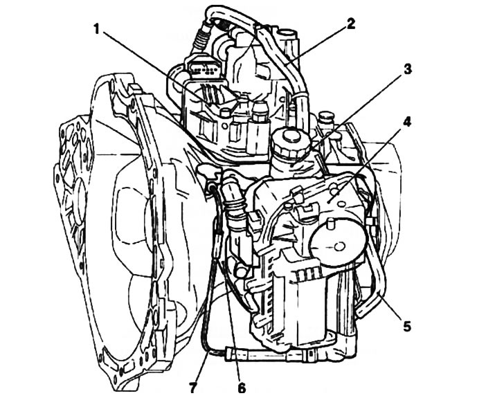
1.3. Easytronic system layout: 1. Gear shift module; 2. Easytronic system cable channel; 3. Brake fluid reservoir; 4. Clutch control module; 5. Clutch hydraulic line supply hose; 6. Clutch control module mounting plate; 7. Return hydraulic line
Visitor comments