
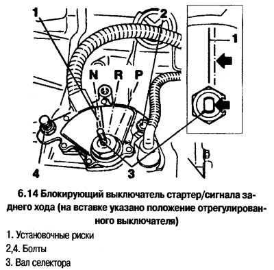
Starter/reverse signal interlock switch
1. The switch is screwed into the front of the transmission case and does two things - prevents the starter from engaging only in selector positions N or P, and turns on the reverse signal in selector position R. If the starter is engaged in positions other than N or P, then the switch is faulty, or its regulation is broken. If the rear light does not turn on, then the switch should be adjusted. If the adjustment does not give a positive result, then replace the switch.
2. Set the selector to position N.
3. Remove the battery and tray.
4. Disconnect a cable from the lever on transmission, turn away a nut and remove the lever.
5. Disconnect the switch connector (located in the wiring harness).
6. On 2.0L engines, remove the fluid level gauge by unscrewing the nut.
7. Bend back the lock washer and unscrew the gear selector shaft nut.
8. Turn away bolts and remove the switch together with a plate and wires, having submitted it upwards.
9. Installation is carried out in the reverse order. Replace fluid level indicator gasket. Adjust switch.
Adjustment (without removing the switch)
10. Adjust the transmission control cable.
11. Set the transmission selector to position N.
12. Remove the battery and tray.
13. Remove the control lever on the transmission by disconnecting the cable from it.
14. When the transmission selector is in position N, the flats on the selector shaft must be parallel to the marks on the switch (see photo). Otherwise, loosen the bolts and set the switch to the desired position.
15. Install the removed parts and battery.
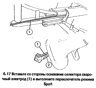
Sport mode switch
16. Remove the selector. (to do this, remove the trim, disconnect the cable and unscrew the 4 bolts).
17. Push the switch out with the welding electrode inserted into the selector hole (see photo).
18. Label the wires and unsolder them from the switch. Remove the wires by pulling them out of the selector.
19. Installation is carried out in the reverse order.
Winter mode switch
20. Remove center floor section (Chapter 11). Loosen the mounting screws on the back of the floor section and remove the selector cover.
21. Remove the indicator panel mounted on the selector overlay from the latches.
22. Disconnect from the switch of a wire and get the switch, having removed from latches.
Kick-down switch
23. The switch is built into the throttle cable, the removal of which is discussed in Chapter 4A.
Transmission processing unit
24. Remove the center floor section (Chapter 11) and left heater duct.
25. Remove the processor unit bracket from the latches on the heater casing and move the unit to the side (cut the harness if necessary). Disconnect the wires from the block, remove the brackets and remove the processor unit.
Transmission Shaft Speed Sensors
26. On 2.0L models, the sensors are mounted on top of the transmission case (see photo).
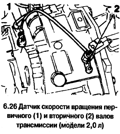
Remove the battery and tray, disconnect the wires from the sensors, unscrew the bolts and remove the sensors (each sensor is bolted).
27. On 1.4, 1.6 and 1.8L models, the sensors are mounted on the rear top of the transmission case. Raise the front of the car, remove the left wheel and the protective fender panel. Disconnect the wires from the sensors, unscrew the bolts and remove the sensors.
Transmission fluid temperature sensor (only for AF20 transmission, 2.0L models)
Attention! The transmission fluid temperature sensor on 1.4, 1.6 and 1.8 liter models is changed at a car service.
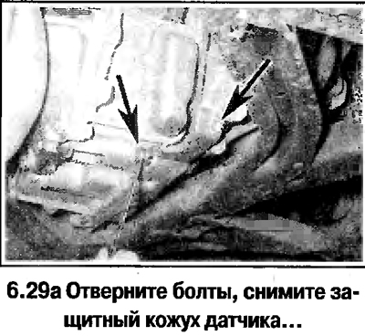
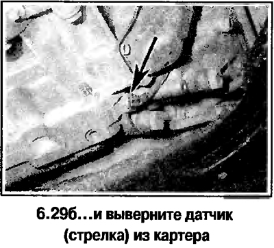
28. The sensor is screwed into the lower front of the transmission case.
29. Raise the front of the car, disconnect the wire from the sensor (the connector is located in the harness next to the sensor), unscrew the bolts and remove the protective casing of the sensor. Unscrew the sensor from the crankcase (see photo).
Visitor comments