


Air conditioning system
The air conditioning system is under constant high pressure. Never disconnect refrigeration lines or remove any system components without first discharging the system. Discharging the air conditioning system must be done by an experienced technician in a car service workshop. Always wear safety glasses when disconnecting refrigeration lines!
Components of a typical air conditioning system (zafira models)
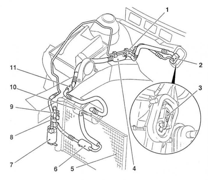
1 — Low pressure circuit service connector
2 - Bolt nipple connection
3 - Expansion valve
4 - Pulsation damper
5 - Capacitor
6 - Pulsation damper
7 — Receiver-dryer
8 — Pressure sensor
9 — High-pressure circuit service connector
10 — Compressor
11 — Bolted nipple connection of the refrigeration pipe
The following checks should be performed on a regular basis to maintain the air conditioning system in good working order:
- Check the condition of the compressor drive belt. If defects or signs of wear are detected, replace it (see Chapter Routine maintenance).
- Check the drive belt tension and adjust if necessary (see Chapter Routine maintenance).
- Check the refrigeration hoses for cracks, swelling, signs of hardening and aging of the rubber, assess the condition of the nipple connections. Replace defective components.
- Check the condenser heat exchanger plates for insect remains, old leaves, and other debris stuck between them. If necessary, clean the gaps with a thin brush or blow them out with compressed air.
- Check the system charge level.
- If you find water leaks on the floor mats under the instrument panel, remove the condensate drain tube from the evaporator housing and use a piece of wire to check the patency of both holes.
The air conditioning system should be turned on for at least 10 minutes at least once a month (even in winter). Long-term inactivity of the K/V leads to hardening and failure of the sealing rings and cuffs of the connecting tract.
The leaks that occur in the tract are best revealed by increasing the operating parameters of the system (temperature and pressure), - leave the air conditioner on for 5-10 minutes with the engine running. Leak sources can be identified by oil drips.
Due to the complexity of the system design and the need to use special equipment, its maintenance, in-depth diagnostics and repair are beyond the skill level of the average amateur mechanic and must be performed in a car service workshop. The car owner is only competent to perform the simplest checks and replacements listed below in this Section.
If the system does not function at all, check the condition of the corresponding fuse and relay.
The most common cause of malfunction of the air conditioner is a decrease in the charge level of the refrigerant oil. The following simple tests will allow you to quickly identify signs of a decrease in the refrigerant level.
Checking the refrigerant charge level
1. Warm up the engine to normal operating temperature.
2. Turn on the air conditioner to maximum cooling capacity. Select the maximum fan speed. Open the doors to avoid cyclic shutdowns of the system when cooling the closed air volume in the cabin.
3. The activation of the A/C compressor clutch is accompanied by a clearly audible click, after which the central part of the clutch should begin to rotate. After the system temperature reaches the operating value, feel the two tubes connected to the evaporator on the bulkhead of the engine compartment.
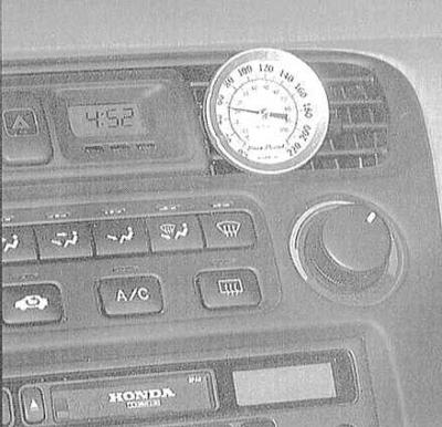
4. The thinner tube going to the evaporator from the condenser outlet should be quite cold to the touch. The thicker tube going from the evaporator outlet back to the compressor should be a little colder (2-6 degrees). If the outlet tube feels noticeably warmer than the inlet tube, the system needs recharging. Insert a thermometer into the outlet air duct through the central deflector on the instrument panel. With the air conditioning on, the temperature of the air coming out of the deflector should be 2-4.5 degrees lower than the ambient temperature (up to 4.5°C). In very hot weather (above 40°C), an increase in the outlet temperature to 15.7°C is permissible, but not more. If the air conditioner does not provide the required intensity of air cooling, the system should be recharged. For a more detailed diagnosis of the system condition, the car should be driven to a specialized workshop.
5. Look into the inspection window, usually provided in the cover of the receiver-dryer assembly - foaming of the refrigerant inside the receiver indicates a drop in its level. In hot weather, bubbles in the inspection window may be present even with a normal level of the working fluid - after the system is turned off, foaming should stop.
Adding refrigerant
Only R-134a refrigerant oil should be used to charge the air conditioning system of the vehicles covered in this manual.
1. Prepare a standard R-134a charging kit (ask in car accessories stores). The kit includes a can of refrigeration oil, a valve nozzle and a section of hose that is connected between the valve and the low-pressure part of the refrigeration line. Only R-134a refrigeration oil should be used, and under no circumstances R-12); the container volume should be 12 ounces (Ounce). Since one can of oil may not be enough to fully charge the system, it makes sense to buy a couple at once just in case. Make sure that at least one of the cans has oil tinted red, which will allow you to quickly identify refrigerant leaks if they occur.
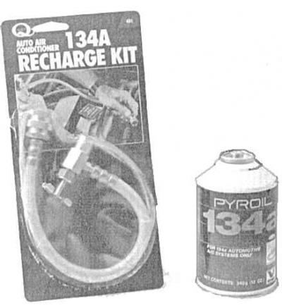
Never fill the system with more than two cans of refrigerant!
2. In accordance with the manufacturers instructions, connect the charging kit to the LOW PRESSURE portion of the refrigeration line.
Do not attempt to connect the kit to the high-pressure part of the tract under any circumstances! The design of the nipple connections allows the kit to be connected only to the low-pressure part of the system.
3. Close the valve on the adapter and screw the latter onto the head of the can, having first checked that the sealing ring/rubber gasket is present.
Be sure to wear safety glasses!
4. Remove the dust cap from the connection of the low-pressure part of the refrigerator path and connect the charging kit hose equipped with a quick-docking connector to it (see the illustration Components of a typical air conditioning system (zafira models)).
The design of the fittings does not allow the set to be connected to the high-pressure part of the tract.
5. Warm up the engine to normal operating temperature and turn on the A/C. Make sure that the charging kit hose does not come into contact with the cooling fan blades or other moving components in the engine compartment.
6. By rotating the valve nozzle, pierce the head of the cylinder, thereby opening the supply of refrigerant (you should hear the characteristic sound of escaping gas). During the entire charging process, hold the can strictly vertically, shaking it from time to time. Charging should be interrupted when the temperatures of the inlet and outlet pipes of the evaporator become equal. Between charging series, make a pause necessary for the system to stabilize.
Never pump more than two cans of refrigerant into the system! To prevent the can from icing during filling, wrap it in a towel soaked in warm water.
7. If you have an accurate thermometer at hand, insert it through the deflector into the central air duct of the air conditioner and use it to monitor the temperature of the air supplied to the cabin.
8. When the can is empty, close the valve and disconnect the hose from the low-pressure fitting of the system. Immediately put the dust cap on the fitting.
9. Disconnect the valve nozzle from the cylinder, if necessary, move it to the second cylinder and continue filling. After completing the procedure, place the unfinished cylinder vertically on the rack and use it to recharge the system as needed.
Heating system
If the heater does not provide adequate heating of the air supplied to the passenger compartment, the cause of such failure may be one of the following:
- The thermostat is stuck open, preventing the engine coolant supplied to the heater heat exchanger from heating up to normal temperature. Replace the thermostat (see Disconnecting and replacing cooling system hoses);
- There is a blockage in the cooling tract, which blocks the supply of coolant to the heater heat exchanger. Feel the hoses connected to the pipes on the rear bulkhead of the engine compartment - both of them should be hot, otherwise the tract is blocked (the hoses, heat exchanger, or heater control valve are blocked). Disconnect the hoses and perform a reverse flow flush of the heat exchanger. Also flush both hoses;
- If it is not possible to restore the heat exchanger's patency by flushing, it should be replaced (see Removal and installation the heater heat exchanger).
- If the heater fan speed does not correspond to the selected position of the corresponding switch on the system control panel, check the condition of the fuse, connecting wiring, relay, switch and resistor assembly (see Removal and installation the resistive assembly of the heater fan drive motor).
- If there is no air outlet through the deflectors at all, take the following steps:
- Turn on the ignition and activate the heater fan. Press your ear to the deflector and try to determine by ear whether the drive motor is functioning;
- If there are no sounds confirming the correct operation of the motor, and the resistive assembly is in order, the electric motor should be replaced (see Removal and installation the heater fan drive motor).
1. Wetting of the carpet on the floor under the heater heat exchanger, or steam escaping through the air duct deflectors indicate heat exchanger leaks. Remove the heat exchanger (see Removal and installation the heater heat exchanger) and replace it with a new one (the heater heat exchanger is not subject to repair).
2. Check the drain hose coming from the heater/evaporator assembly and running along the right side of the bulkhead for leaks. A blockage in this hose may cause steam to leak from the air vents when the heater is turned on.
Eliminating Air Conditioning Odors
Unpleasant odors, which often occur when the air conditioner is turned on, are caused by the formation of mold colonies on the evaporator heat exchanger plates. A warm, humid environment creates favorable conditions for the emergence and development of fungal microorganisms.
Access to the evaporator heat exchanger on most models is extremely limited. The procedure for guaranteed complete mold removal, performed in a car service workshop, is quite labor-intensive, time-consuming and requires the use of strong disinfectants. In principle, quite effective treatment can be performed at home by the car owner himself.
1. Special disinfectants in aerosol packaging designed for servicing air conditioning systems can be purchased at almost any car accessory store. It should be remembered that the price of the product is usually directly proportional to its effectiveness. Switch the system to closed air circulation mode and turn on the heater fan at maximum speed for ten minutes. In order to dry the system, turn on the heating at maximum intensity. Disconnect the wiring from the compressor in order to prevent it from operating.
2. The product is usually supplied through a long hose. Remove the resistive assembly of the heater fan drive electric motor (see Removal and installation the resistive assembly of the heater fan drive motor), insert the nozzle of the feeder into the resulting hole and move it to the left, directing it at the evaporator heat exchanger. The product is fed in accordance with the manufacturer's instructions. Try to treat the entire surface of the heat exchanger as completely as possible. The duration of each treatment cycle and the intervals between series must be indicated on the container label.
Visitor comments