
For the old 2.0L engine and the 2.4L engine, the V-belt is tensioned by alternator displacement. For the correct tension of the belt in car workshops, a special measuring tool is used, the use of which is not discussed here. In general, the belt in the center of the maximum distance between the pulleys should sag 12-13 mm under the influence of the thumb.
Engine 2.0 l OHC (until mid-1995 release) and 2.4 l engine
As already mentioned, the belt tension is checked with a special measuring device. During temporary control, the belt tension of the 2.0L engine of the former model and the 2.4L engine is checked as follows:
1. Press with your thumb in the middle of the maximum distance between the pulleys. Check if the deflection corresponds to the set value.
2. If necessary, loosen the tension bar (engine 2.0 l) or tension screw nut (engine 2.4 l) and the lower alternator mounting bolt and press the alternator out (2.0 l) or turn the tension screw (2.4 l) so as to tighten the belt.

3. While holding the alternator in this position, tighten both loose bolts to 25 Nm (2.0 l) or tighten the tension screw nuts (2.4 l). After adjustment, check the belt tension. The tension screw of the 2.4 l engine is shown in illustration.
The V-belt is replaced as follows:
Engine 2.0 l
Replacement is carried out after loosening the generator mounting, as described above. Check belt tension after replacement.
Engine 2.4 l
If equipped with air conditioning, the compressor drive V-belt must be removed before replacing the water pump drive belt. It is also necessary to remove the power steering pump drive belt.
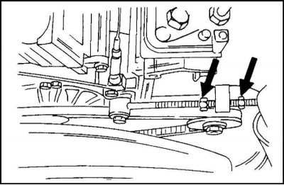
1. Loosen both nuts shown in fig. arrows, and unscrew the tension screws so as to loosen and remove the belt.
2. Put on a new V-belt and adjust its tension with the tension screw, as described above. Tighten the nuts to a torque of 25 Nm.
Engine 2.0 l since the middle of 1995 of release
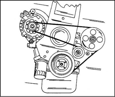
1a. V-belt routing diagram for a 2.0L engine since 1995 and a DOHC engine without air conditioning.
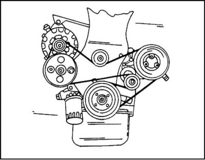
1b. V-belt routing diagram for 2.0L engine since mid-1995 and for DOHC engine with power steering pump and air conditioning.
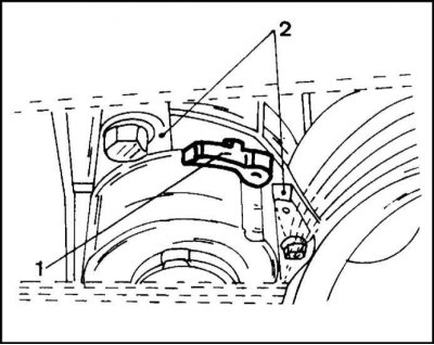
1c. On illustration. 1a and 1b show a multi-ribbed belt routing diagram for an engine with and without a power steering pump. The belt tension is maintained automatically by the tension roller. Only the movable tension lever can be checked, as shown in fig. 1c. If the tension lever (1) is not between two stops (2), then replace the V-belt and tension roller. The replacement is as follows:
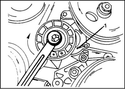
2. Install the key as shown in the illustration on the tension roller and turn it in the direction of the arrow (clockwise). This loosens the tension on the belt and it can be removed. If the belt is reinstalled, it is necessary to mark the direction of rotation on the belt with paint or a felt-tip pen. To hold the tension roller, you can insert the pin in the place indicated in the illustration (1).
3. Put the belt on all the pulleys and pull the pulley back and then press it against the belt. When the engine is started for the first time, the belt tension is reset automatically.
Due to the fact that the belt is multi-ribbed, it is important to correctly lay it in the grooves of the pulleys. After that, remove the pin from the tension roller and release the roller onto the belt again.
Sometimes you have to replace or remove the belt tensioner. In this case, after removing the belt, turn the roller in the direction shown in fig. point 2 so that the pin (1) entered into the opening intended for him. Turn out both bolts of a tension roller and remove a roller.
During installation, the roller is again fixed with a pin (1). Tighten the bolts to 18 Nm. The belt is put on, the pin is removed and the tension roller is pressed against the belt.
DOHC engine
Tension control and belt replacement are carried out similarly to the belt of the 2.0 liter engine, manufactured from mid-1995. Before removing, it is necessary to paint an arrow on the outside of the belt with paint indicating the direction of rotation of the belt if the belt is to be installed again. The tension roller is replaced in the manner described above.
Visitor comments