
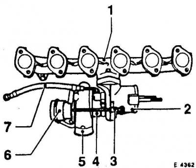
1. Exhaust manifold
2. Turbocharger
3. Boom air control valve
4. Oil return connection
5. Compressor body
6. Discharge pressure control valve
7. Oil line
Intake manifold parts
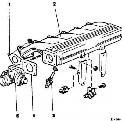
1. Gasket
2. intake manifold
3. Charge air temperature sensor
4. Gasket
5. Exhaust gas return valve Warning! Remove the cylinder head only when the engine is cold.
The exhaust and intake manifolds are unscrewed from the cylinder head and left on the vehicle.
A faulty cylinder head is recognized by various signs.
Vehicles without air conditioning
Removing
1. Disconnect the battery ground cable.
Warning! This erases data from the electronic memory, such as the radio's security code.
2. Remove the bottom shield of the engine compartment.
3. Drain the coolant (also from the cylinder block).
4. Drain the engine oil.
5. Take out a vacuum hose with a corner on the brake booster.
6. Disconnect the thin vacuum tubes at the vacuum hose check valve.
7. Unscrew the air injection tube on the cylinder head and disconnect the air hoses after loosening the clamps.
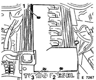
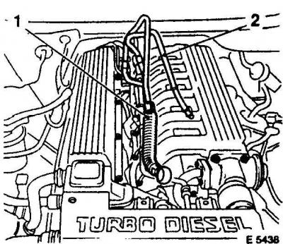
8. Unscrew the engine top cover and remove it (1, 2, 3 - screw).
9. Remove the engine ventilation hose on the cylinder head cover, as well as the intake air hose from the air filter housing and turbocharger, to do this, loosen and slide the clamps back.
10. Unscrew the exhaust manifold from the cylinder head. In this case, first loosen the bolts evenly from the outside to the inside, first by half a turn, then completely loosen. Unscrew the exhaust manifold (3 bolts) on the turbocharger.
Warning! Cover the turbocharger openings with a clean rag and make sure that no foreign objects get into the supercharger, as serious engine damage may occur.
11. Remove the exhaust manifold gaskets from the engine. Note the installation position: the gasket brackets face away from the engine.
12. Remove the intake manifold from the cylinder head.
13. To do this, disconnect the cable at the charge air temperature sensor, disconnect the vacuum hose at the EGR valve and at the underside of the intake manifold.
14. Loosen the charge air tube and disconnect it.
15. Unscrew the intake manifold on the cylinder head and holder and remove with gaskets.
16. The exhaust gas return valve with gasket does not need to be unscrewed.
17. Unscrew the injection lines using a slotted ring wrench from the injection pump and injectors.
Warning! Do not change the shape of the piping bend.
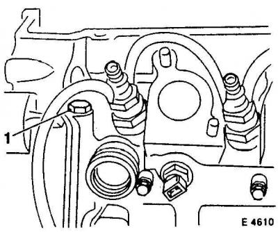
18. Disconnect the coolant hose from the thermostat housing by loosening the hose clamp.
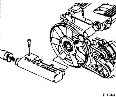
19. Remove the multi-ribbed V-belt.
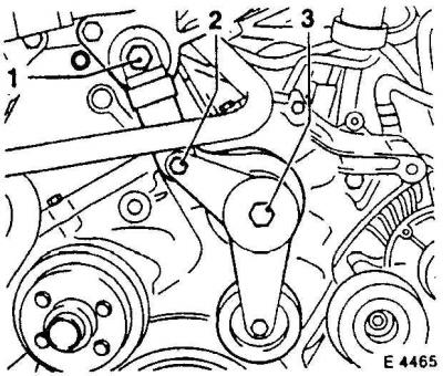
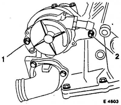
20. Remove the multi-ribbed V-belt tensioner. To do this, unscrew the bolts (1 and 2) damper, as well as a cork (3), when removing and installing, watch the gasket.
Warning! The tensioner damper can only be stored in a standing position. If storage rules are accidentally violated, it can be made usable again by squeezing it vertically several times.
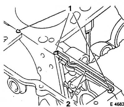
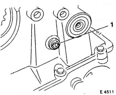
21. unscrew the bolts (1) And (2).
Installation
1. Remove gasket (1) cylinder heads. The thickness of the gasket is indicated by holes. Gaskets are available with 2 and 3 marks. A gasket of the same thickness must be installed.
2. If work has been carried out on the crank mechanism, the gasket thickness must be re-determined (performed from the workshop).
3. Clean the sealing surface of the cylinder block with a suitable scraper.
4. Make sure that dirt does not get into the holes of the cylinder block.
5. Cover the holes with a rag.
Warning! The cylinder head bolt holes must be free of oil and coolant residue. Blow out the holes with compressed air or wrap a rag around the screwdriver and dry the holes. Otherwise, pressure will be generated when screwing in, which may lead to cracking of the cylinder block or incorrect tightening torque.
6. Clean the sealing surface of the cylinder head.
7. Check the evenness of the surface of the block and cylinder head.
Warning! Sealing surfaces cannot be machined.
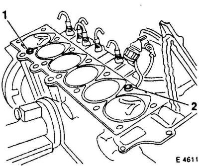
8. Correctly insert guide bushings (1 and 2).
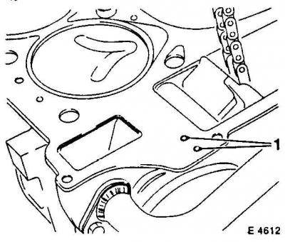
9. Insert a new sealing strip (2) into the groove of the sealing surface of the cylinder block (1 - connection).
10. Apply sealant OPEL 15 03 294 to the joint.
11. Apply a new head gasket of the same thickness. Inscription "TOR" should be facing up towards the cylinder head. The channels must not be blocked by a gasket.
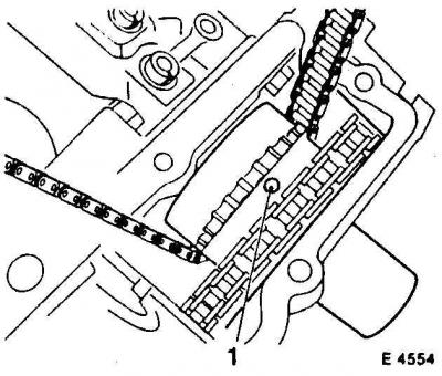
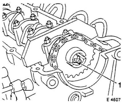
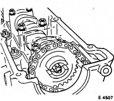
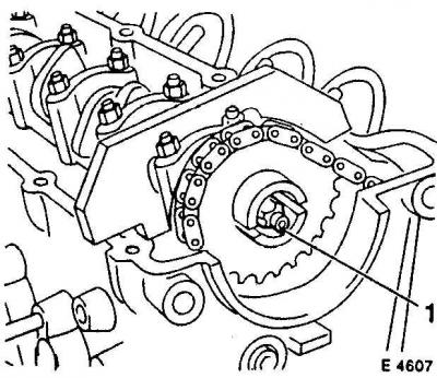
12. Before installing the cylinder head, make sure the mark (1) sprockets of the injection pump are facing up.
13. Otherwise, remove the test rod on the flywheel and rotate the crankshaft 1 turn forward until the mark is facing up and the test rod can be inserted again.
14. If the camshaft was removed, after installing the shaft, pause for 10 minutes before installing the head. Otherwise, the hydraulic pushers will not have time to sit down and there will be a danger of the pistons colliding with the valves.
15. Carefully place the head on the gasket with the help of an assistant. In this case, the camshaft must be fixed in the TDC position of the piston of the 1st cylinder.
16. Pass the chain through the head.
17. Use new cylinder head bolts.
18. Coat the bolts with engine oil on the threads and their head surfaces.
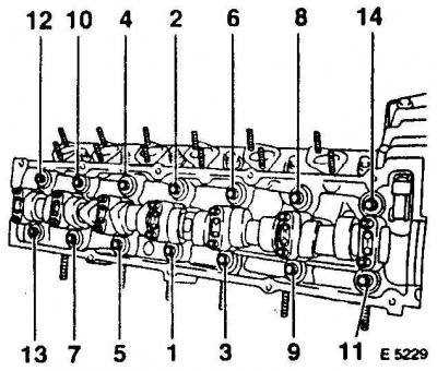
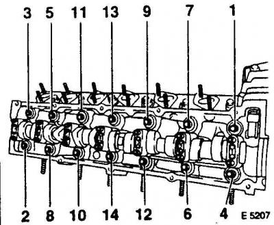
19. Tighten the bolts with a torque wrench crosswise from the inside to the outside with a force of 80 N.m.
20. On the second pass, loosen the bolts in a spiral from the inside to the outside by 180° (1/2 turn).
21. On the third pass, tighten the bolts crosswise in a spiral from the inside to the outside with a torque of 50 N.m.
22. On the fourth pass, tighten the bolts 90°further (1/4 turn).
23. On the fifth pass, tighten the bolts an additional 90°.
24. In order to accurately maintain the 90°angle, it is advisable to mark the camshaft housing cover accordingly.
25. To do this, install the key on the bolt and mark with chalk at a distance of 90°, if necessary, cut out a 90°template from cardboard.
26. Such a template is also available from HAZET 6690.
Warning! After assembling the engine and 25 minutes of warm-up, the cylinder head bolts must be tightened by 90°.
27. Screw in the pin securing the upper drive chain guide rail.
28. Unscrew a bolt of fastening from the block of cylinders.
29. Connect the plugs to the glow plugs and both coolant temperature sensors.
30. Connect the plug of the start of injection sensor on the injector of the 4th cylinder.
31. Install the chain on the sprocket.
32. Tighten the oil spray nozzle by hand.

33. Press the chain tensioner with the KM-822 lever, while pulling out the fastening pin (2) (1 - bolt).
34. Check the valve timing with a special tool (1). The crankshaft is in the TDC position of the piston of the 1st cylinder. At the same time, the adjusting device must be in contact on both sides with the sealing surface of the cylinder head.
Warning! This only applies to new drive chains or those under 20,000 km.
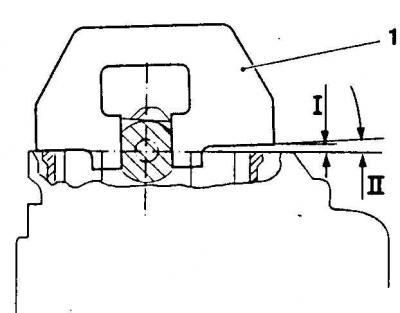
35. For chains over 20,000 km, to compensate for the extension on the intake side under the locking device (1) need to put a gasket (flat feeler) (I) 4.61 mm thick. This corresponds to an angle of 2° (II), to which the camshaft is turned.
36. In this position, screw on the sprocket with the new oil spray nozzle (1 - channel).
37. Holding the camshaft by the hexagon with a wrench, tighten the bolt to 20 Nm, then tighten it 35°with a hard wrench.
38. In order to accurately maintain an angle of 35°, it is advisable to mark the cylinder head accordingly. To do this, place the key on the bolt and mark with chalk at a distance of 35°, if necessary, cut out a template from cardboard. Such a template is also available from HAZET 6690.
39. Remove the locking devices on the crankshaft and camshaft and rotate the crankshaft 2 turns.
40. Reinsert the test rod into the flywheel (1 - pin).
41. The camshaft tester should now be inserted in the same way as before tightening the sprocket.
42. Repeat the adjustment if necessary.
43. Insert vacuum pump with new O-ring and new bolt (2), while the drive cams enter the camshaft sprocket (1 - bolt).
44. Lubricate the seal with petroleum jelly or silicone grease before installation. Connect the vacuum line.
45. Install the fuel lines to the fuel filter.
46. Connect the upper hose from the radiator to the cylinder head, as well as the heater coolant hose from the tube, secure with clamps.
47. Screw on the multi-ribbed V-belt tensioner.
48. Screw the damper on the cylinder head with a force of 40 N.m., on the guide lever with a force of 20 N.m.
49. Screw the plug onto the pin and tighten to 20 N.m.
50. Screw the bolts.
51. Screw the injection pipes on the injection pump and injectors with a force of 25 N.m.
52. Install the exhaust manifold, replace all gaskets.
53. The gasket brackets between the exhaust manifold and the cylinder head point away from the head. Screw the exhaust manifold onto the turbocharger (3 bolts) with a force of 45 N.m., on the cylinder head with a force of 25 N.m., tighten the bolts crosswise from the inside out.
54. Screw the intake manifold on the cylinder head with a force of 25 Nm, replace all gaskets.
55. Screw the oil filter housing support and the exhaust gas return valve pipe to the intake manifold with a force of 25 N.m.
56. Insert the vacuum hose with the angle piece on the brake booster.
57. Connect thin vacuum lines to the vacuum hose check valve.
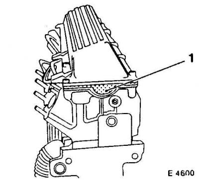
58. Install the cylinder head cover with a new gasket (1) and screw from inside to outside with a force of 15 N.m. Observe the installation position of the gasket on the rear side of the cylinder head.
59. Connect the crankcase ventilation hose, secure it with a clamp.
60. Screw the coolant line holder onto the cylinder head cover.
61. Install the crankcase breather hose to the cylinder head cover and the intake air hose from the air filter housing and turbocharger, secure with clamps.
62. Install the engine top shield.
63. Screw the charge air pipe on the cylinder head, install the air hoses, secure with clamps.
Cars with air conditioning
Removing
1. Remove the viscous fan and air diffuser on the radiator.
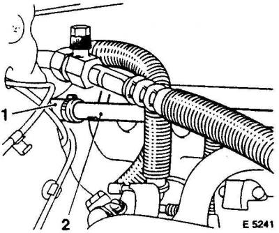
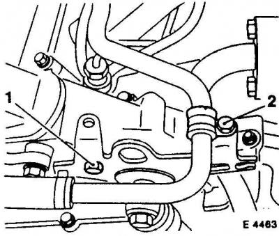
2. Disconnect the upper coolant hose (1) from the radiator on the cylinder head, as well as the heater coolant hose from the pipe (2) after loosening the hose clamps.
3. Remove both fuel lines (1 and 2) on the fuel filter. The supply pipe is slightly thicker than the return pipe.
4. Collect the leaking fuel with a thick cloth.
5. Release the pipes from the fasteners and slightly raise, unscrew the fuel lines by about 130°counterclockwise. Make sure that the pipes are not bent.
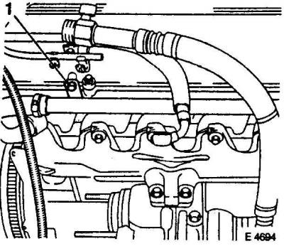
6. Unscrew holder (1) coolant pipe from the cylinder head cover.
7. Disconnect the engine ventilation hose from the cylinder head cover by loosening the hose clamp.
8. Unscrew and remove the cylinder head cover.
9. Disconnect all cable plugs.
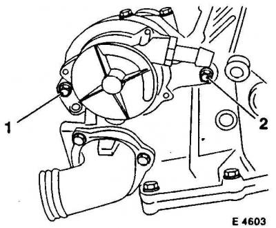
10. unscrew the bolts (1 and 2) on the vacuum pump.
11. Disconnect the vacuum line.
Warning! Bolt (2) at the same time it serves to fasten the upper chain guide bar. It should always be replaced, as it has a micro-notch for fixation.
12. Set the piston of the 1st cylinder to the TDC position.
13. To do this, place the transmission in neutral and apply the handbrake. Install a bent box wrench or ratchet socket onto the belt pulley center bolt.
14. Slowly turn the crankshaft clockwise by hand until the cams of the first cylinder are simultaneously facing up.
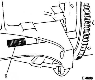
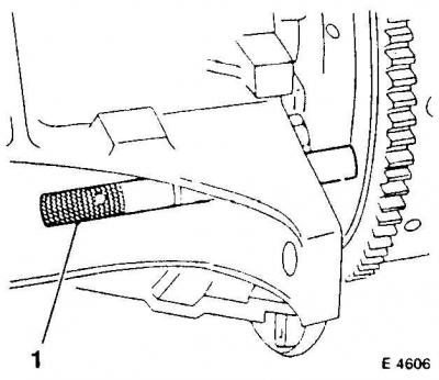
15. In this position, the test rod (1) (OPEL KM-813) through the hole in the cylinder block can be inserted into the hole in the flywheel.
16. You can use another suitable rod, for example, a drill.
17. Remove the existing plug and install the rod.
Warning! Insert the rod only to check the TDC position, do not use it to fix the crankshaft.
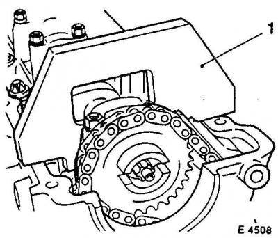
18. Lock the camshaft with a locking device OPEL KM-811 (1). The tool must rest on both sides on the sealing surface of the cylinder head cover. It holds the camshaft in the TDC position of the piston of the 1st cylinder. If there is no such device, make such a device yourself.
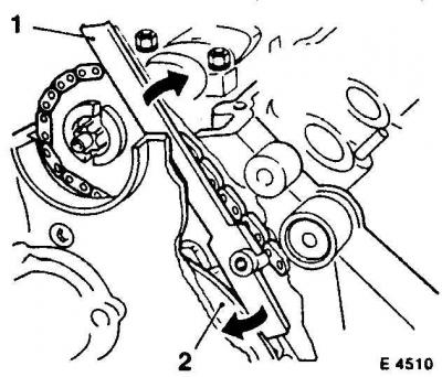
19. Install lever KM-822 (1) between the upper tensioner bar and the fastening pin and press the tensioner bar in the direction of the arrow (2 - installation location). This weakens the drive chain.
20. When loosening the drive chain with the lever (1) you can insert the KM-823 mounting pin into the tensioner hole (2 - location).
21. First unscrew the plug at the pin installation site. The chain tensioner is fixed with a pin. Hold the camshaft by the hex key with a wrench.
22. Unscrew the oil nozzle (1) from the camshaft sprocket.
23. Take off the star.
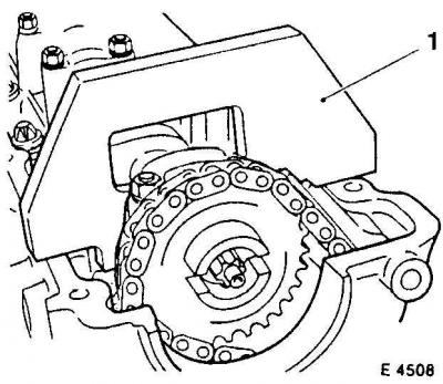
24. Unscrew the bolts of the timing gear housing.
25. Unscrew the nut (1) fastening the stud on the camshaft drive housing.
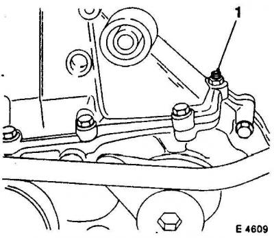
26. unscrew the bolt (1) fasteners from the cylinder block.
27. Disconnect the plugs from the glow plugs and from both coolant temperature sensors on the cylinder head.
28. Disconnect the plug of the start of injection sensor on the injector of the 4th cylinder (4th cylinder in front).
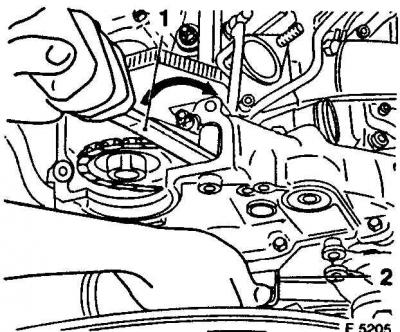
29. unscrew the pin (1) securing the top chain guide.
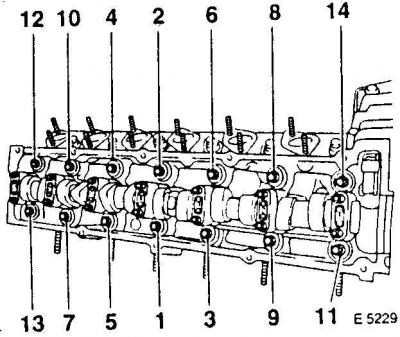
30. Loosen the cylinder head bolts in sequence from outside to inside, first a half turn, then another half turn.
31. Remove the cylinder head with an assistant.
Warning! When removing, make sure that the top guide rail of the drive chain is not damaged and that the chain does not remain hanging on the cylinder head. Place the head on a wooden board so as not to damage the sealing surface.
Installation
1. Install the viscous fan and air diffuser on the radiator.
2. Check all plugs and hoses, connect if necessary.
3. Fill with coolant.
4. Install the multi-ribbed V-belt.
5. Check engine oil level, top up if necessary. If the cylinder head was removed due to a faulty head gasket, change the oil and oil filter as there may be coolant in the engine oil.
6. Connect the mass cable to the battery. Set the time on the clock, set the security code of the radio.
Warning! Remove the test rod and close the hole with a plug.
7. Establish the bottom guard of an impellent compartment.
8. Start the engine and warm up for 25 minutes.
9. Remove the cylinder head.
10. Tighten the cylinder head bolts from the inside to the outside in sequence with a 90°hard wrench (1/4 turn), without loosening them first.
11. Screw the coolant line holder onto the cylinder head cover.
12. Install the crankcase ventilation hose on the cylinder head cover, as well as the intake air hose from the air filter housing and turbocharger, secure with clamps.
13. Screw on the engine top shield.
14. Screw the charge air pipe on the cylinder head, install the air hoses, secure with clamps.
Visitor comments