
Single vape (SOHC) engines
1. Decompress the fuel system (Chapter 4A) and disconnect the battery from the ground.
2. Remove the drive belt. Drain the coolant.
3. Remove the air filter and intake duct.
4. Remove the top section of the throttle body by undoing the screws and disconnecting the hoses.
5. Designate and disconnect sockets of the wires which are passing near to an inlet collector. Remove the wires from the brackets and brackets.
6. Turn away bolts of fastening of an arm of the generator to a collector. Take the generator with the bracket to the side.
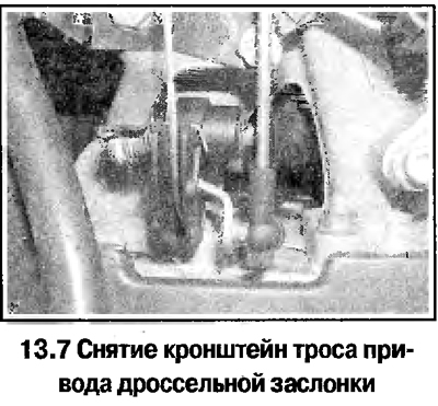
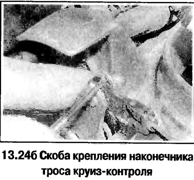
7. Disconnect the throttle cable and remove the cable bracket from the manifold (see photo).
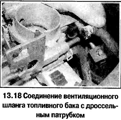
8. Disconnect all hoses from the manifold and throttle (see photo), unscrew the nuts and remove the manifold.
9. When assembling, replace the manifold mounting nuts, as well as all gaskets and seals of the disassembled connections. Tighten the manifold nuts evenly and gradually in a diagonal pattern.
Twin-shaft engines 1.4 and 1.6 liters
10. Remove the upper engine cover by unscrewing the screws and removing the oil filler plug.
11. Remove the air filter and air duct.
12. Remove the alternator drive belt tensioner and remove the belt.
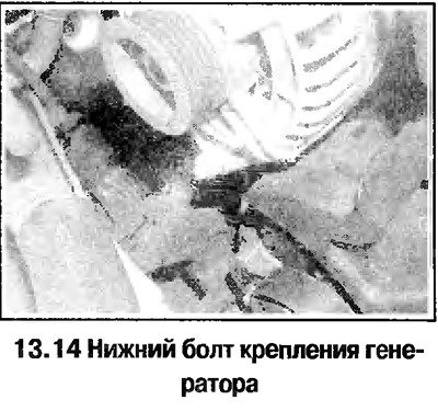
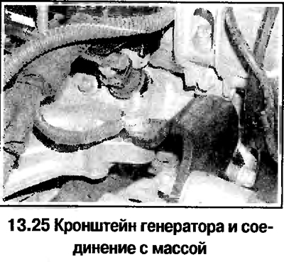
13. Turn away bolts of fastening of an arm of the generator in the right part of a collector.
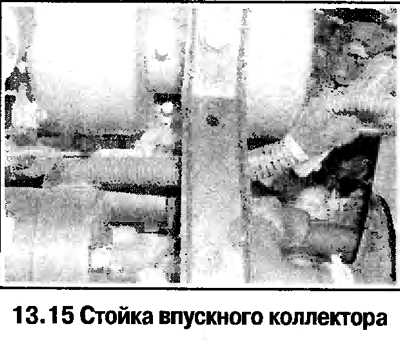
14. Loosen the lower alternator mounting bolt and move the alternator to the side by turning it (see photo).
15. Remove the manifold stand (see photo).
16. Remove nozzles with fuel distributor.
17. Disconnect the throttle cable from the throttle body.
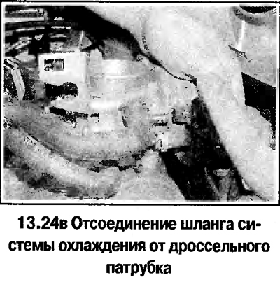
18. Label and disconnect all wires and hoses from the manifold and throttle pipe (see photo).
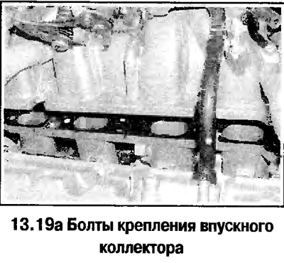
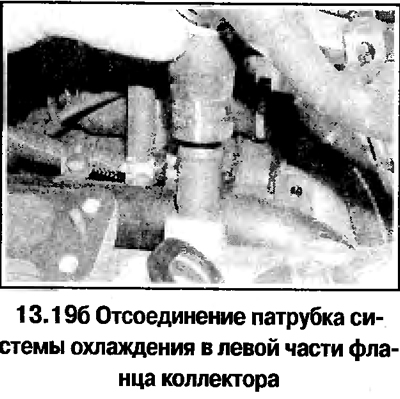
19. Turn away 5 bolts and remove a collector. To remove the manifold flange, disconnect the hose (see photo) and unscrew 9 nuts. Further disassembly of the collector is highly discouraged.
20. Installation is carried out in the reverse order. Replace all gaskets and seals of disassembled joints. Tighten the manifold and flange nuts and bolts evenly and gradually in a diagonal pattern.
Engines 1.8 and 2.0 l
21. Remove the alternator belt, decompress the fuel system and disconnect the battery from the ground.
22. Remove the upper engine cover by unscrewing the screws and removing the oil filler plug
23. Release the clamps and disconnect the air duct with the air flow meter from the throttle pipe and air filter. On Zafira models, this will require removing the engine compartment seal, deflector panels under the windshield and the cover above the engine compartment bulkhead.
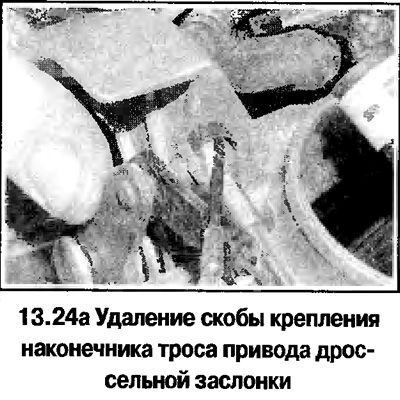
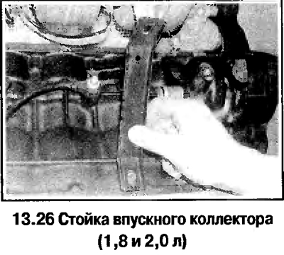
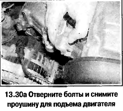
24. Label and disconnect from the intake manifold and throttle pipe all accessible wires and hoses and cables (see photo). Remove the cable brackets from the throttle body.
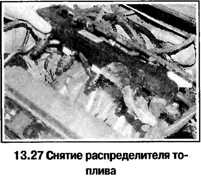
25. Disconnect the generator bracket from the manifold and move the generator to the side along with the bracket (see photo).
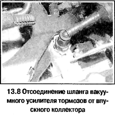
26. Remove the manifold stand by unscrewing the bolts (see photo).
27. Disconnect the fuel lines and hoses from the fuel distributor. Remove the fuel distributor with injectors and wiring box and connectors (see photo).
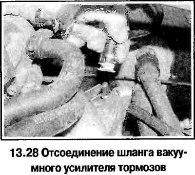
28. Disconnect the vacuum brake booster hose from the manifold (see photo) and heater hoses.
29. On 1.8L models, remove the engine processor unit (see above), on 2.0L models, disconnect the tube from the clutch master cylinder
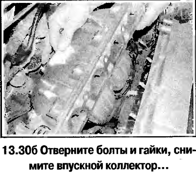
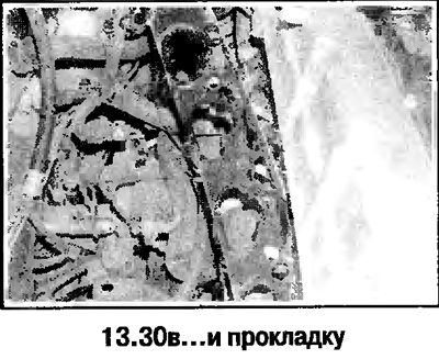
30. Remove the manifold by completing the final steps (see photo). Further disassembly of the collector is not allowed.
31. Installation is carried out in the reverse order. Replace the manifold mounting bolts, all gaskets and seals of the disassembled joints. Tighten the manifold bolts evenly and gradually in a diagonal pattern. Bleed air from hydraulic clutch (1.8 l), adjust the cables and belt tension.
Visitor comments