
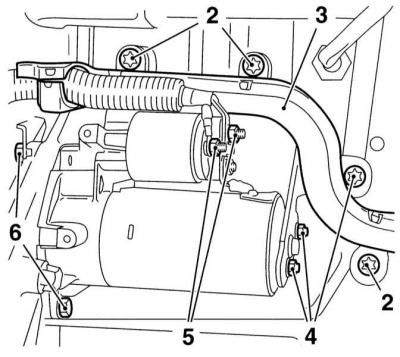
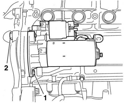
2 — Bolts of fastening of a route trench of an electrical wiring
3 - Routing chute of electrical wiring
4 — Bolts of fastening of a basic arm of an exhaust manifold and a back arm of a starter
5 — Nuts of fastening of an electrical wiring of the traction relay
6 — Bolts of fastening of a starter
Removing
1. Disconnect the negative cable from the battery, jack up the front of the car and place it on jack stands. If equipped, remove the crankcase protection.
Petrol models
SOHC engines
1. Give two fixing nuts and disconnect electric sockets from the traction relay of a starter. Remove the washers under the nuts.
2. Give a fixing nut and disconnect a ground wire from the top bolt of a starter.
3. Give a nut of a fixing bolt and, having lowered a starter down, take it from the car.
DOHC engines
1. Turn out fixing bolts and remove a basic arm of the inlet pipeline.
2. Give two fixing nuts and disconnect conducting from the traction relay, - remove the washers put under nuts.
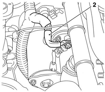
3. Give a fixing nut and disconnect a ground wire from the top bolt of fastening of a starter.
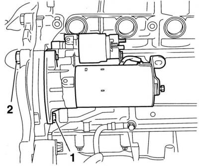
4. Loosen the nut of the mounting bolt and, lowering the starter down, remove it from the car - pay attention to the difference in the lengths of the mounting bolts (top bolt (1) longer than the bottom (2)).
Diesel models
Engine 1.7 l SOHC
1. Remove intake ducts with MAF sensor (see chapter Power and exhaust systems).
2. Remove the alternator drive belt (see chapter Current service).
3. On right-hand drive models, remove the alternator (see Removal and installation of the generator).
4. Remove the exhaust manifold (see chapter Power and exhaust systems).
5. Disconnect the electrical wiring from the starter traction relay.
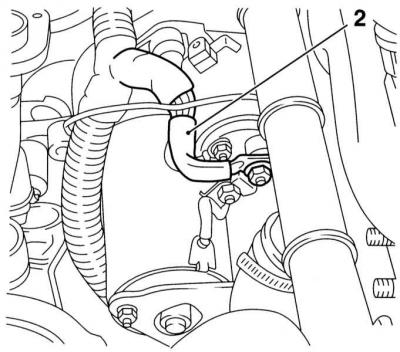
6. Turn out the top bolt of fastening of a starter from transmission side.
4. Remove the lower bolt of fastening of a starter from outside the engine. Remove the starter through the top of the engine compartment.
Engine 1.7L DOHC
1. Disconnect the oil drain tube connecting the oil filter housing to the engine block at the rear of the latter - prepare to collect spilled oil.
2. Remove the atmospheric pressure sensor (BARO) (see chapter Power and exhaust systems). Remove the mounting bolts and remove the sensor bracket from the ECM support bracket.
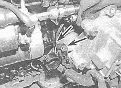
3. Give a fixing nut and the screw and disconnect an electroconducting from the traction relay of a starter. Remove the washers under the nuts (refer to illustration).
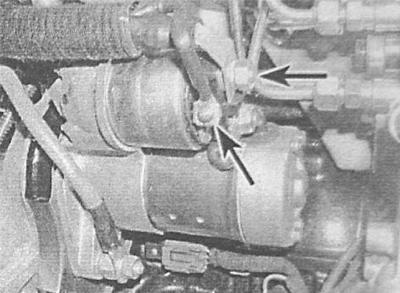
4. Give a fixing nut and disconnect a ground wire from the bottom bolt of fastening of a starter.
5. Unscrew the mounting bolts, lower the starter down and remove it from under the car, - and remove the starter through the bottom from under the car, - pay attention to the difference in the lengths of the mounting bolts (bottom bolt is longer).
2.0 liter engines
1. If equipped, remove the crankcase protection.
2. Turn out two fixing bolts and remove the thermofilter of a starter.
3. Turn out bolts of fastening of conducting to a back part of the block of cylinders (see illustration Starter Installation Diagram).
4. Remove the mounting bolts and remove the exhaust manifold support bracket from the cylinder block (see illustration Starter Installation Diagram).
5. Give two fixing nuts of fastening and disconnect an electroconducting from the traction relay of a starter. Remove the washers under the nuts.
6. Turn out three fixing bolts and remove the heat-shielding screen of a turbocharger.
7. Remove the starter mounting bolts, the upper bolt is installed on the right side, the lower bolt is on the transmission side (see illustration Starter Installation Diagram). Lift the starter up and remove it from the engine compartment.
Installation
All models
Installation is in the reverse order.
1. Make sure that the wiring is installed correctly and that the requirements are met Specifications fastener tightening force.
Visitor comments