


Contents: Position of seats and headrests ⬇ Headrests ⬇ Active head restraints ⬇ Front seats ⬇ Armrest ⬇ Rear bench seat ⬇
Position of seats and headrests
The driver's seat should be adjusted to a position that provides the driver with maximum comfort when operating the pedals, gearshift lever/AT selector, steering wheel, and instrument panel switches. In addition, adequate visibility through the windshield and side windows and reliable restraint of the driver's body by the seat belt should be ensured. The authors of this Manual recommend that the driver's seat be adjusted so that the driver can hold the steering wheel by the rim slightly above the center spokes, with the arms at the elbows slightly bent.
The design of the car seats guarantees maximum comfort for the person sitting in them, while simultaneously providing conditions for the most effective performance of their functions by the seat belts and airbags. Soft padding of the cushions and backrests provides additional protection for the driver and passengers in emergency situations.
Attention! The use of any additional pillows or other objects placed on the seat cushion or back is not permitted!
The choice of seat position also affects the safety of the occupant. For example, if the front seat is moved forward too far, the risk of injury to the occupant increases when the airbag is deployed, as well as the risk of being thrown through the windshield in a frontal collision. Moving the driver's seat back affects the ease of use of controls while driving. Increasing the angle of the seatback will worsen the fixation of the body by the seat belt - the more the backrest is tilted back, the higher the likelihood of the occupant's body slipping under the lap section of the belt in a strong frontal impact, and the more severe the injuries may be. It is recommended to set the angle of the backrest 25-30° from the vertical position. Lock the front seat in the most remote position (convenient for driving) from the steering wheel/dashboard position, bring the backrest to the most comfortable, preferably vertical, position.
Important elements of the safety system are head restraints. They prevent injury to the cervical spine and head in the event of a rear impact. It is necessary to check the adjustment of the head restraints before each trip (see below). The adjustment of the seats should be done before starting to move. After completing the adjustment, make sure that the backrest and the entire seat assembly are securely fixed.
Headrests
Warning! Headrests are an additional means of ensuring safety in the event of an accident, never remove them when driving! They are designed to work together with seat belts - do not forget to fasten the belts!
Adjustment
Attention! Adjustment of head restraints is mandatory! Only correctly installed head restraints provide adequate protection against possible damage to the cervical vertebrae in a rear impact!
The headrest should be adjusted in height so that its central part is at the same level as the eyes/upper edge of the ear of the occupant (see illustration 12.1), - if it is not possible to achieve this condition, the headrest should be set to the uppermost position (for tall people) or to the extreme bottom (for short people) position.
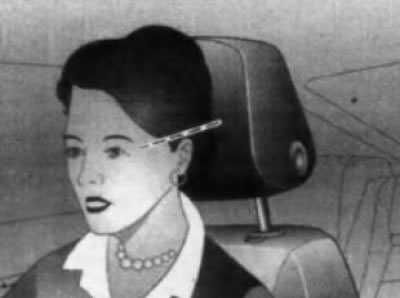
12.1 Correct adjustment of the headrest
To adjust the height of the headrests of the front and rear side seats, press the button (see illustration 12.2) on the side of the headrest and manually move it up or down to the desired angle. If necessary, you can adjust the tilt of the headrest by pushing its lower side forward or backward (see illustration 12.3)
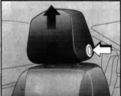
12.2 Adjusting the height of the front and rear outboard head restraints
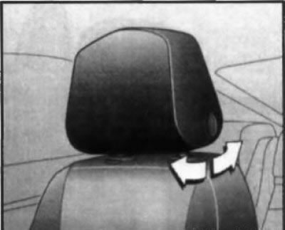
12.3 Adjusting the angle of the head restraint of the front and rear outboard seats
On models with the appropriate equipment for adjusting the built-in (non-removable) rear bench seat head restraints, the corresponding head restraint must be pulled forward with both hands (in the direction of travel) and adjust the height of the headrest by pulling it up or down (see illustration 12.4).
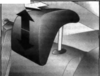
12.4 Adjusting the integrated head restraint of the rear bench seat
Removal
To remove, hold down the headrest locks, pull the headrest up and release it from the guides (see illustration 12.5). The integrated head restraints of the rear bench seat cannot be removed. When not in use, the head restraints must be moved to the lowest position.
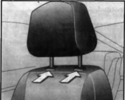
12.5 Removing the headrests
Installation
To install, insert the headrest rods into the receptacles on the seat back and, pressing them with a little force, lower the headrest down.
Active head restraints
Warning! Correct adjustment significantly increases the effectiveness of the head restraints - be sure to adjust the active head restraints as described above! Never tie or hang anything on the head restraint rods!
Active head restraints (with appropriate equipment) reduce the likelihood and severity of neck injuries in a rear-end collision. The installation of active head restraints on seats is indicated by the inscription "ACTIVE" (see illustration 12.6) on the seat guide bushings. At the moment of impact, the active head restraint moves forward under the influence of the inertial force of the passenger's body on the seat back and helps to reduce the dynamic backward tilt of the head, reducing the load on the cervical vertebrae. The head restraint then returns to its original position. Active head restraints are especially effective in collisions at low and medium speeds, at which (as statistics show) accounts for the majority of cases of neck injuries to drivers and passengers.
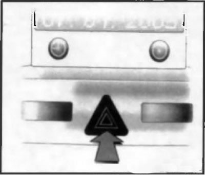
12.6 Designation of active head restraints
Front seats
Attention! Adjustment of the seat position should only be performed when the vehicle is stationary!
Adjustment
Manually operated adjustment mechanism
To move the front seat longitudinally, pull up on the release lever located under the outer front edge of the cushion, then slide the seat assembly to the desired position and release the lever (see illustration 12.7).
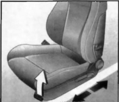
12.7 Adjusting the front seat assembly position in the longitudinal direction
To check the reliability of the seat fixation in the new position, try to move it. The seat back angle is adjusted using the rotary handle located on the outer side surface of the back (see illustration 12.8).
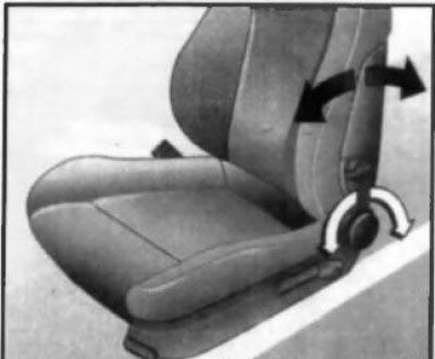
12.8 Adjusting the front seat backrest angle
Note: When making adjustments, remove your body weight from the seat back.
The design of the front seat back also allows for adjustment of the lumbar portion. Adjustment is made using the lever handle located on the outer side surface of the seat back(see illustration 12.9).
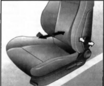
12.9 Adjusting the front seat lumbar support
Note: When making adjustments, remove your body weight from the seat back.
If equipped, the front seat cushion can be adjusted. The height of the cushion is adjusted by rocking the lever (see illustration 12.10), located at the back on the outer side of the pillow (up - to increase, down - to decrease the height)The angle of the cushion is adjusted in a similar way using another lever (see illustration 12.11), located in front on the outside of the cushion.
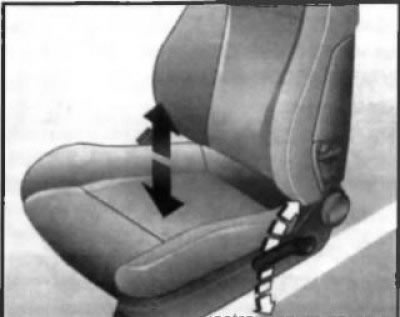
12.10 Adjusting the height of the front seat cushion
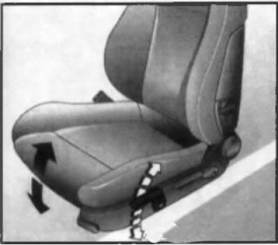
12.11 Adjusting the front seat cushion tilt
Electric adjustable mechanism
Attention! The electric seat adjustment motor is equipped with an automatic protection system for the electric circuit against overloads - if the motor stops during adjustment, wait approximately 30 seconds, then continue the adjustment operations! Do not use the electric seat adjustment for a long period of time with the engine off!
On models with the appropriate equipment, the front seat position is adjusted using two lever switches located on the outer side of the seat cushion (see illustration 12.12). To adjust, pull the corresponding switch and hold it until the seat reaches the desired position. Using the horizontally located multi-function switch (see illustration 12.12)the position of the seat cushion is adjustable:
- To change the tilt of the cushion, press the front part of the switch up or down;
- To change the height of the cushion, press the rear part of the switch up or down;
- To move the seat in the longitudinal direction, press the switch in the longitudinal direction forward or backward.
To adjust the seat backrest angle, press the top of the vertically located switch (see illustration 12.12) forward or backward. In addition, on models equipped with electric front seats and rear-view mirrors, a module with a memory function for the positions of the seats and mirrors can be installed. The control panel for the module is located above the lever switches (see illustration 12.13) and allows you to save 3 different positions of the seat and mirrors in the module's memory. This function is activated when the ignition is turned on and also continues to function for approximately 10 minutes after the ignition is turned off, the key is removed from the ignition switch and the driver's door is opened/closed. When the car is locked, the function will be deactivated until the above-mentioned period has elapsed.
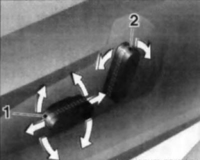
12.12 Lever switches for adjusting the position of the seat cushion (1) and backrest tilt (2)
To enter the settings into the module's memory, you must first adjust the seats (see above) and rear-view mirrors, and then simultaneously press the "M" memory access button and one of the three functional number buttons in the memory cell of which you want to enter the setting. The end of recording the information is confirmed by a sound signal.
The parameters stored in the module memory are recalled by holding down the corresponding function button on the control panel until the seats and mirrors are set accordingly.
Note: Retrieving settings from the module memory is only possible when the vehicle is stationary.
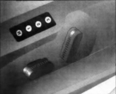
12.13 Control panel for the memory module for the front seats and rear-view mirrors
In models of this configuration, when locking the car using the remote control, the current position of the driver's seat and rear-view mirrors is remembered, and for each remote control separately. To recall the saved settings from the module's memory, you must unlock the car using the remote control and open the driver's door within a minute after unlocking - the seat and mirrors will automatically be set to the position remembered for this remote control. If necessary, the automatic adjustment process can be stopped by pressing one of the lever switches of the electric drive.
Armrest
On models with the appropriate configuration, a folding armrest can be installed between the front seats. To lower the armrest, you need to press it and lower it to a horizontal position - in this position, the armrest can be pulled forward (see illustration 12.14)
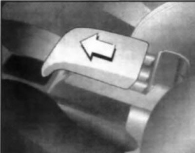
12.14 Installing the front seat center armrest
The armrest may be equipped with a storage box. To open the box, move the armrest to the extreme rear position, press the locking button in the front part of the armrest and fold back the lid (see illustration 12.15). When closing, make sure that the lid is securely fixed.
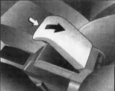
12.15 To access the front armrest storage compartment, press the latch and open the cover
Folding
On models with the appropriate equipment, the backrest of the front passenger seat can be folded down to the cushion.
First lower the headrest to its lowest position, check the reliability of its fixation. Move the front seat back a little, pull the lever up (see illustration 12.16), located on the outer side of the seat back and fold the seat forward until the lock clicks into place.
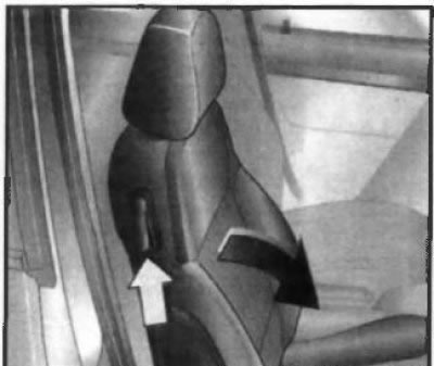
12.16 Folding the front passenger seat backrest
Unfolding is done in the reverse order; it is imperative to check the reliability of the backrest fixation in the upper position.
Rear bench seat
The vehicles covered in this Manual may be equipped with a two-piece rear seat (with asymmetric division), or a three-section design.
Armrest
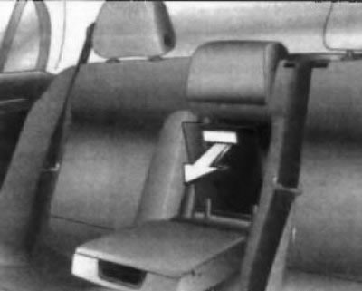
12.17 Folding down the rear bench seat hatch cover
The rear seat can be equipped with a folding armrest, intended for use when there are fewer than three passengers in the rear seat. To move the armrest into the working position, pull it by the upper edge/handle and lower it horizontally. If necessary, fold the hatch forward (see illustration 12.17), located in the wall of the pocket under the armrest in the back of the rear seat - skis or other long objects can be pushed through the resulting window. The hatch cover can be locked from the luggage compartment, for which it is necessary to turn the handle on its back side 90° clockwise in the closed position of the cover (see illustration12.18): horizontal position of the handle - the lid is locked; vertical - the lid is unlocked. If equipped accordingly, the ability to transport long loads is also ensured by folding the backrest of the central section of the rear seat.
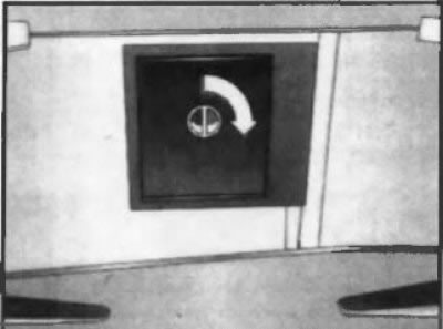
12.18 Locking the rear bench seat hatch cover
Folding
If you need to expand the luggage space for transporting large-sized cargo, the back of the rear seat can be folded. The split design of the rear bench seat allows you to fold any section independently of the others. Before folding the backs, you must move the headrests to the lowest position (all the way) (see above), move the front seats slightly forward, if the rear seat armrest was used before, it must be folded. Put the seat belt buckles away from the seat niche.
The release handles for the backrest locks are located on the outer sides of their upper edges (see illustration 12.19)To fold the backrests, push the handles forward (in the direction of the vehicle's movement) and fold the seat backs down against the seat cushions, then move the front seats to the most comfortable position.
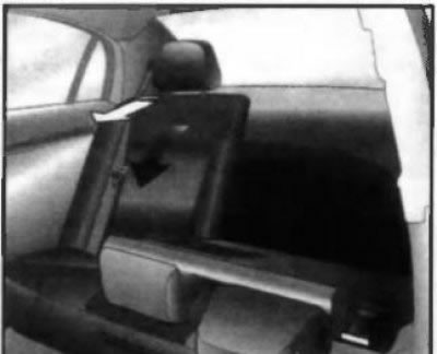
12.19 Folding the rear seat backrest
The backrests are unfolded in the reverse order. The backrest must be raised until the lock clicks - check the reliability of the backrests in the vertical position. Make sure that the rear seat belts take their standard positions when the backrests are raised.
Note: The three-seat safety belt of the central rear seat can only be pulled out of the inertia return device if the backrest of the multi-seat seat is locked in an upright position.
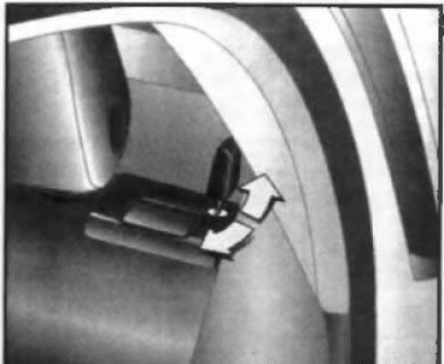
12.20 Locking the folding of the rear bench seat backrests
If equipped, the folding function of the rear bench seat backrests can be locked by inserting the key into the lock cylinder (see illustration 12.20), located next to the lock release handle, and lock the lock by turning the key 180°.
Visitor comments