
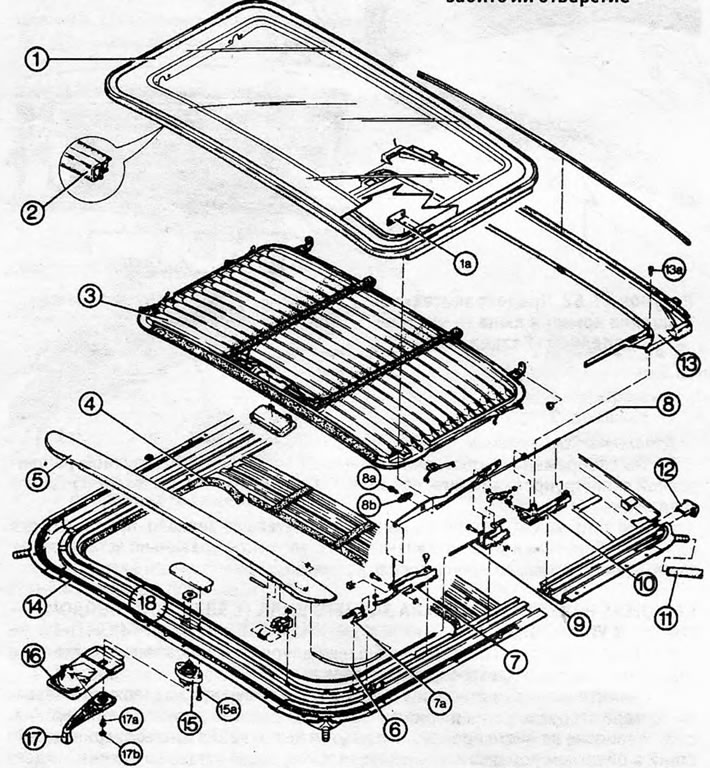
Figure 11.70. Detailed view of sliding/tilting manhole cover parts 1. Glass panel; 1a. Clamp; 2. Rubber seal; 3. Sun visor; 4. Gasket; 5. Wind deflector; 6. Lift; 7. Front guide; 7a. Sliding block; 8. Sliding block guide; 8a. Screw; 8b. Locking plate; 9. Cable; 10. Drain guide; 11. Drain hose; 12. Guide plug; 13. Gutter; 13a. Gutter screw; 14. Gasket; 15. Crank drive; 15a. Screw; 16. Back plate of the handle; 17. Crank drive handle; 17a. Screw; 17b. Screw cover; 18. Frame;
1. The processes described in this Section do not require complete removal of the hatch structure from the vehicle.
Glass panel
2. Close the panel and slide the canopy all the way back. Remove the clips from the side rails.
3. Unscrew the panel from the side guides on both sides and remove it (see Figure 11.71).
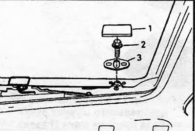
Figure 11.71. Sliding block guide design - cover shown (1), guide bolt (2) and locking plate (3)
4. Before installing a new panel, measure the distance between the flanges. Bend flanges as necessary to ensure required measurement (see Figure 11.72).
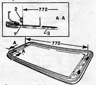
Figure 11.72. Distance between flanges when installing panel (measurements are given in mm) 1. Flange; 2. Nut sheet; 3. Protective
5. Remove the protective sheet from the new panel and install it in place. Lift the panel to "oblique" position and place it on its guides without securing it.
6. Before tightening the side rail screws, close the panel and adjust its position as shown in Figure 11.73, and then tighten the screws.
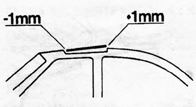
Figure 11.73. Glass panel installation position
Control gasket
7. "Control gasket" - This is a rubber strip surrounding the glass panel.
8. Remove the glass panel as described above.
9. Disconnect and remove the rubber sealing strip and clean off any old putty, taking care not to damage the glass.
10. Apply putty (GM 90140944, or similar) around the edge of the glass panel (see Figure 11.74).
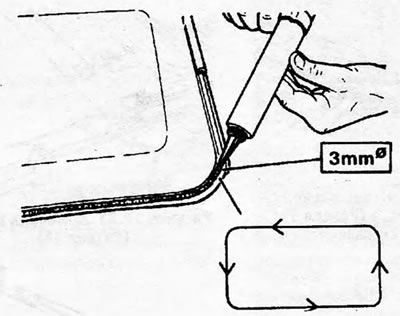
Figure 11.74. Apply putty to the glass panel as shown
11. Install the new rubber strip, starting from the middle of the left edge and working around the perimeter. Immediately install the panel and ensure that the rubber strip is properly seated in the closed position. If the specified composition has been used, it will take at least an hour for it to set and harden, during which time the position of the sealing strip may be slightly adjusted to ensure the most suitable position. Make sure the panel is correctly adjusted in height (see point 6).
Gutter
12. Remove the glass panel as described above.
13. Remove the two Torx screws that secure the gutter. Remove the drain from the slot in the roof (see Figure 11.75).
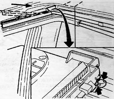
Figure 11.75. Removing the Gutter - Inset Shows the Location of the Mounting Tabs
14. Install the drain into the slot at a certain angle, inserting it so that the holding tabs fit into the drain guides.
15. Install and tighten the Torx screws.
16. Install and adjust the glass panel.
Sun visor
17. Remove the drain as described above.
18. Carefully release the four visor springs from the roof guides using a plastic tool to avoid damage. Remove the visor from its guides (see Figure 11.76).
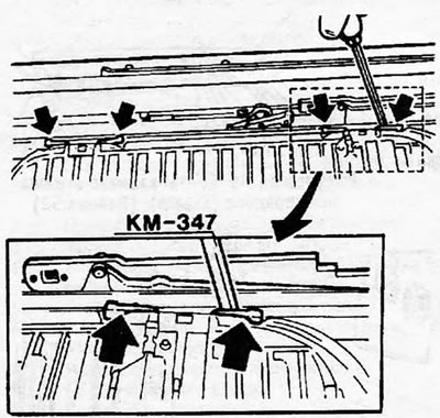
Figure 11.76. Position of sun visor retaining springs - indicated by arrows
19. Reinstall by performing the above steps in reverse order. Make sure that the ends of the springs fit into the guides.
Crank drive
20. Unscrew the central mounting screw from the handle - the screw head is hidden by a plastic cover. Remove the handle and detach its back plate - be careful not to damage the headliner.
21. Unscrew the two mounting screws and remove the crank drive mechanism.
22. When installing a new mechanism"crank drive, adjust it as follows.
23. If the hatch cover is open, temporarily install the drive and close the cover, then remove the drive again.
24. Rotate the drive gear by hand - not the control knob - until the locking pin comes out of the housing (see Figure 11.77).
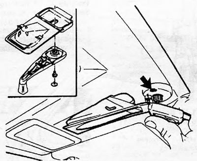
Figure 11.77. Crank drive and handle design (The arrow indicates the position of the locking pin)
25. Reinstall and secure the crankshaft with the locking pin facing forward. Install the back plate and handle.
Wind deflector
26. Remove the glass panel as described above.
27. Using the handle, push the side blocks back until the wind deflector can be accessed and removed.
28. Transfer the lifters and bearing blocks to the new reflector; secure them with spring clips (see Figure 11.78).
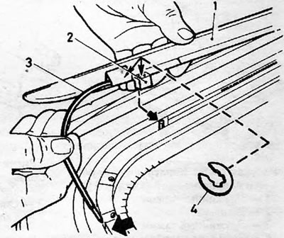
Figure 11.78. Wind deflector mounting design.; 1. Wind deflector; 2. Fastening; 3. Lift spring; 4. Retaining clamp
29. Install the new wind deflector, return the side blocks to the closed position and replace the glass panel.
Visitor comments