
Note: Use new flywheel/drive plate mounting bolts and cylinder head mounting bolts.
1. Turn over the block of cylinders, wipe saddles of loose leaves of radical bearings.
2. Insert the main bearing shells into the crankcase. Note that the rear bushing contains thrust flanges.
3. Lubricate the liners with clean engine oil.
4. Gently lower the crankshaft into the crankcase. Rotate it a few times and check that it is correctly placed.
5. Check that the crankshaft side play is within specifications by inserting wood chips between the main bearing ribbed bush and the crankshaft thrust surface.
6. Clean the rears of the lower main bearing shells and caps, then reinstall them. Lubricate the bearings with clean oil.
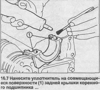
7. Apply a suitable sealant to the mating surfaces of the rear main bearing cap (Opel recommends using a GM spec 15 04 200 seal (Part no. 08 983 368)) (see illustration).
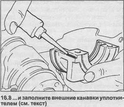
8. Fill the grooves on each outer edge of the rear main bearing cap with a sealant ball approximately 6mm in diameter (Opel recommends seal GM specification 15 03 294 (Part no. 90 001 851)) (see illustration).
9. Establish all covers of radical bearings, establish bolts of fastening of covers. Tighten the bolts by hand, then tighten them evenly with the specified tightening torque. Check that the grooves in the rear main bearing cap are tight enough and wipe off any excess sealant.
10. Turn the crankshaft and check that it rotates freely without jamming.
11. Lubricate the lugs of the new crankshaft rear oil seal. Slide the oil seal onto the crankshaft, with the rib inward, and press it into the rear main bearing cap.
12. Lay the cylinder block on its side, lubricate the cylinder bores and crankshaft journals with oil.
13. Position the piston rings around the pistons so that their cut gaps are 180°apart. For the oil scraper ring, shift the cuts in the upper and lower parts by 25-50 mm to the right and left of the gap in the cut of the central part.
14 Clean the backs of the connecting rod bearing shells and caps, then reinstall the shells.
15. Turn the crankshaft so that the #1 cylinder neck is at BDC.
16. Install a piston ring plier on the #1 piston, then insert the piston into the #1 cylinder with the arrow on the piston head towards the front end of the engine (to the drive chain).
17. Use a hammer handle to drive the piston through the ring compressor into the cylinder, directing the connecting rod to the neck.
18. Install the connecting rod crumb, then insert the bolts. Tighten the bolts evenly and with the tightening force specified in the Specification.
19. Check that the crankshaft rotates freely, taking into account the resistance of the piston rings.
20. Repeat the procedure given in steps 15-19 with the remaining pistons.
21. Turn over the block on the bench.
22. Install the keyway into the crankshaft groove. Install the drive chain sprocket and distributor/oil pump drive.
23. Clean the threads of the drive chain guide and camshaft sprocket base plate bolts, coat them with blocking compound. Install the guide and plate, tighten the bolts securely.
24. Install the flywheel / drive plate on the crankshaft, screw in new mounting bolts, a bolt with a mark «R» install in the position marked during removal; on models with automatic transmission, be sure to install a gasket and washer between the crankshaft and the drive plate. Having blocked the crankshaft with the tool shown in illustration 9.10, tighten the fastening bolts with the tightening force regulated by the Specification.
25. Turn the crankshaft so that cylinder No. 1 is at TDC and align the mark on the flywheel/drive plate with the pointer on the cylinder block.
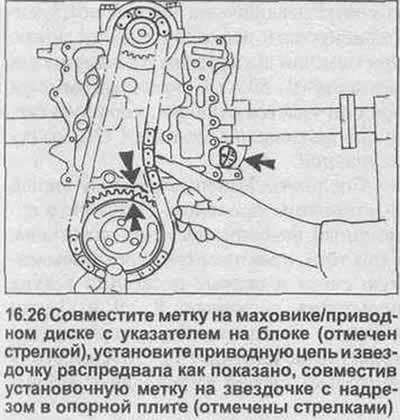
26. Install the camshaft sprocket and drive chain assembly to the engine, aligning the marks made during removal. Pulling the chain taut on the left side, remove any slack on the right side of the chain and check that the ignition point on the camshaft sprocket is aligned with the notch on the base plate (see illustration). If necessary, disconnect the chain and adjust the position of the sprocket.
27. Install drive chain tensioner blades and mounting bracket (s) in place.
28. Using a screwdriver, carefully remove the oil seal from the drive chain front cover. Install the new one, with the tab inward, and press it into place.
29. Insert the drive chain cover location pins into the block, install new gaskets.
30. Establish a covering of a driving chain and insert bolts of fastening. Tighten the bolts with the torque specified in the Specification.
31. Completely clean the mating surfaces of the block and head.
32. Check that cylinder #1 is still at TDC. The mark on the flywheel/drive plate is aligned with the pointer, the alignment mark on the camshaft sprocket is aligned with the notch in the base plate. Install the drive chain tensioner and O-ring, screw it in a couple of turns.
33. Check that the location pins are inserted into the block and apply a suitable sealant (Opel recommends seal GM spec 15 03 294 (Part no. 90 001 871)) in the area of the connection between the cover of the drive chain and the cylinder head.
34. Install a new 'O' ring in the recess at the top of the drive chain cover, then install the new cylinder head gasket, making sure it is properly oriented and seated on the pins.
35. Check that the camshaft recesses are correctly installed, and carefully lower the cylinder head into place.
36 Carefully insert the new cylinder head bolts into the holes (don't drop them!) and screw in only by hand, as far as possible.
37. Uniformly in the sequence shown in an illustration 12.22, tighten bolts of fastening of a head of the block of cylinders the moment of a stage 1.
38 Tighten the bolts again in the sequence shown to the stage 2 angle.
39. Wait approximately ten minutes, and then turn the bolts in a circle to the stage 3 corner.
40. Install the two smaller bolts at the front end of the cylinder head, tighten them with the tightening torque specified in the Specification.
41. Put an asterisk on the end of the camshaft, tighten the fastening bolts with the tightening force regulated by the Specification. Check that the flywheel/drive plate and camshaft sprocket timing marks are correctly set, then clamp the drive chain tensioner with the tightening torque specified in the Specification.
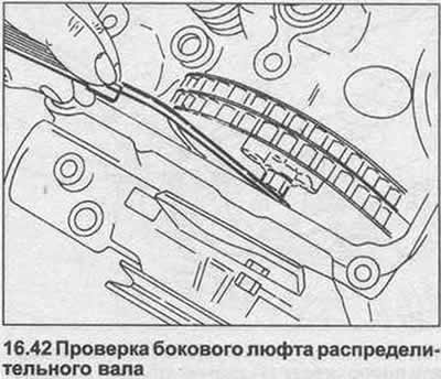
42. Screw in the new plastic side play bolt (included in the gasket set) end of the camshaft, then install the access plate and new gasket on the front end of the cylinder head. Using a feeler gauge, measure the gap between the side play bolt and the protective cover; this is the side play of the camshaft (see illustration). Set the required clearance by screwing in the camshaft side play bolt.
43. Install the inlet to the actuator cover base using a new gasket. Apply a blocking compound to the mounting bolts and tighten them securely.
44. Check that the surfaces of the pallet and block are clean and dry.
45. Apply a suitable sealant (Opel recommends using a GM spec 1503 294 seal (Part no. 90 001 851)) in the area of \u200b\u200bcontact with the block with the drive cover and the rear cover of the main bearing.
46. Secure the shims in their positions, insert the rubber shims into the grooves in the drive chain cover and bearing cap and gasket in the base of the cylinder block. Check that the joints between the gaskets are sealed.
47. Clean the threads of the pan mounting bolts, apply a blocking compound to them. (Opel recommends the use of GM specification blocking compound 15 10 177 (Part no. 90 167 347)).
48. Attach the pallet and install the mounting bolts. Tighten all bolts by hand, then tighten them in a circle with the tightening torque regulated by the Specification.
49. Install the water pump using a new gasket, insert the mounting bolts. Tighten the fastening bolts with the torque specified in the Specification.
50. Carefully slide the crankshaft pulley assembly into place, being very careful not to damage the oil seal boss, and align the groove with the crankshaft key. Install the pulley mounting bolt, tighten it with the tightening torque regulated by the Specification, blocking the flywheel / drive disk.
51. Adjust valve clearances as described in Chapter 13.
52. Install the cover gasket on the cylinder head, and install the cover. Install the cover bolts and tighten them securely.
53. Install glow plugs and injectors.
54. Install the dipstick for measuring the oil level.
55. Install the oil pressure sensor and tighten it securely.
56. Install accessories listed in Chapter 8.
Visitor comments