
This section is devoted to the description of maintenance and repair procedures for some elements of the on-board electrical system. In addition, the procedures for diagnosing malfunctions of electrical equipment of a general order are considered.
Opel began to install the Controller Area Network device (CAN). It combines individual control devices into a common circuit (data bus), which gives the following advantages: fast data transfer from one device to another, saving space due to the use of small boards and parts, reducing the number of sensors due to their multifunctionality.
How CAN works
Instead of a separate conductor, only two common wires are used for each signal, which allows you to simultaneously receive information about the status of most devices and sensors without using separate toggle switches and switches.
CAN bus receiving important information (for example, about a malfunction), fixes it in its memory.
Safety
When repairing electrical equipment and the engine power system, disconnect the wire from the terminal «–» battery.
When replacing fuses, it is forbidden to use screwdrivers and metal tools, as this can lead to a short circuit in the circuits of electrical equipment.
It is forbidden to disconnect the ignition switch and the battery while the engine is running, as this will lead to failure of the voltage regulator and elements of the vehicle's electronic equipment.
When checking the circuits of electrical equipment, it is forbidden to short to «mass» wires (check the continuity of the circuits «for a spark»), as this can lead to failure of electrical components.
Do not even briefly connect the output «30» generator with «weight» (check the generator «for a spark»), as this will lead to failure of the generator rectifier unit diodes. You can only check the alternator on a car with a voltmeter and an ammeter. In order to avoid failure of the diodes of the rectifier unit, it is forbidden to check them with a megohmmeter or a test lamp supplied with a voltage of more than 12 V, and also to check the electrical circuits on the car with such devices without disconnecting the wires from the generator. It is necessary to check the insulation resistance of the generator stator winding with increased voltage on the generator removed from the vehicle, with the stator winding terminals disconnected from the rectifier unit.
When carrying out electric welding work on a car, it is necessary to disconnect the wires from the battery terminals and the generator.
Do not touch the elements of the ignition system and high-voltage wires while the engine is running.
Do not run low voltage and high voltage wires in the same bundle.
When recharging the battery in a car using a charger, disconnect the wires from the battery terminals.
Checking the presence of supply voltage
Checks for the presence of supply voltage are made in the event of a malfunction of the electrical circuit. Connect one of the circuit tester leads to either the negative battery terminal or a well-grounded point on the vehicle body. Connect the other tester lead to the electrical connector terminal of the circuit under test, preferably the one closest to the battery or fuse. If the tester's control lamp lights up, the supply voltage is present on this section of the circuit, which confirms the health of the circuit between this point in the circuit and the battery. Continuing in the same way, explore the rest of the chain. Detection of the absence of supply voltage indicates the presence of a malfunction between this point in the circuit and the last one previously checked (where the supply voltage was present). In most cases, the cause of the failure is the loosening of the electrical connectors and the deterioration of the quality of the contacts themselves (oxidation).
Searching for a short circuit
One method for finding a short circuit is to remove the fuse and connect a probe lamp or voltmeter instead. There should be no voltage in the circuit. Pull the wiring while watching the probe lamp. If the lamp begins to flash, there is a short to ground somewhere in this wiring harness, possibly caused by chafing of the wire insulation. A similar check can be made for each of the components of the electrical circuit by turning on the appropriate switches.
Grounding check
This check is made to determine the reliability of the grounding of the circuit element. Disconnect the battery and connect one of the wires of the self-powered probe lamp to a known well-grounded point. Connect the other lamp wire to the wiring harness to be tested or the electrical connector terminal. If the lamp lights up, ground is OK (and vice versa).
Open circuit checks
The test is carried out in order to detect breaks in the electrical circuit. After turning off the power to the circuit, check it with a probe lamp equipped with an independent power source. Connect the probe wires to both ends of the circuit, if the test lamp lights up, there is no open circuit. If the lamp does not light up, then this indicates an open circuit in the circuit. In the same way, you can check the health of the switch by connecting a probe to its terminals. When the switch is turned to position «On» the probe lamp should light up.
Break location
When diagnosing a suspect for an open section of an electrical circuit, visually detecting the cause of a malfunction turns out to be quite difficult, since it is difficult to inspect the terminals for corrosion or a violation of the quality of their contacts, due to limited access to them (usually the terminals are covered by the body of the electrical connector). A sharp twitch of the connector housing on the sensor or its wiring harness in many cases leads to the restoration of contact. Do not forget about this when trying to localize the cause of the suspected failure for an open circuit. Intermittent failures can be caused by terminal oxidation or poor contact quality.
Diagnosing faults in electrical circuits is not an intractable task, provided it is clear that the electric current is supplied to all consumers (lamp, electric motor, etc.) from the battery through wires through switches, relays, fuses, fuses, and then returns to the battery through the mass of the car body. Any problems associated with the failure of electrical equipment can only be caused by the interruption of the supply of electric current to them from the battery or its return to it.
Wires, fuses and relays
Protection of the vehicle's electrical circuits from short circuits is ensured by the use of a combination of fuses, circuit breakers and fuse links. A blown fuse is easy to distinguish from a good one by examining its transparent plastic case. Carefully inspect the fuse for a blown fuse. If the fuse looks normal on the outside, but suspicions of its malfunction have persisted, check the continuity between the knife terminals protruding from its body.
When replacing fuses, make sure that the value of the new fuse matches the value of the old fuse. Fuses designed for different amperages may look the same on the outside, so special attention should be paid to the marking. Replacing a blown fuse with one designed for a smaller - and especially a large - current strength is undesirable. Every electrical circuit needs a different degree of protection. Make sure that the marking on the fuse box corresponds to the current strength for which the corresponding circuit is designed. If the replaced fuse blows immediately, it would not be wise to keep replacing it. First of all, you should identify and eliminate the cause of its burnout. In most cases, this turns out to be a short circuit in the electrical circuit caused by a break or damage to the wire insulation.
Fusible links
Protection of some electrical circuits is carried out by including fusible links in them. Inserts are typically used to protect non-fused circuits such as the ignition circuit.
Fuses are similar to fuses in that their failure (reflow) easily determined visually.
To replace the fuse, disconnect the negative cable from the battery. Remove the burnt insert and install a new one in its place. Before replacing an insert, be sure to try to determine the cause of the overload that caused the failure of the insert.
Circuit breakers (thermal relays)
Thermal relays protect components such as power windows, door locks and headlight adjustment (electrocorrectors). Some of the circuit breakers are installed in the mounting block. The return of thermal relays to their original state on some models is carried out automatically, i.e. when an overload occurs in the circuit, the thermal relay instantly opens, then, after cooling, returns to its original state. If the circuit does not return to working position, it should be checked immediately. The normal functioning of the thermal relay confirms the health of the circuit. Some of the breakers are equipped with push buttons for manual forced reset.
Replacing fuses
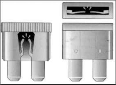
To prevent short circuits and overloads of consumers of electrical energy, individual circuits are protected by fuses. Opel vehicles use state-of-the-art fuses, these fuses have blade contacts.
Before replacing a fuse, be sure to switch off the relevant consumer first.
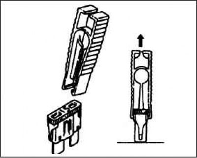
Pry off the fuse box cover with a narrow screwdriver and remove it.
A blown fuse is recognized by the melted metal strip. The location of the fuses is shown on the inside of the fuse box cover.
Remove the defective fuse with the plastic tweezers located in the cover of the fuse box.
Insert a new fuse of the same rating (current strength).
If a newly inserted fuse blows after a short time, check the corresponding electrical circuit.
Never replace the fuse with wire or similar aids, as this could cause serious damage to the vehicle's electrical system.
It is recommended that you always have a set of spare fuses of different ratings in your car. A suitable place is provided for their storage in the fuse box.
The fuse rating is printed on the back of the fuse box. In addition, the housing has an appropriate color, which can be used to determine the rated current.
Relays are used to supply electric current to some elements of the vehicle's electrical equipment. Failure of the relay to function properly leads to failure of the element it serves. If any of the relays is suspected to be defective, it must be removed and checked at a service station or a specialized car workshop. Replacing a failed relay is done as an assembly.
Visitor comments