
Removing
Models F13, F17 and F18
The shift mechanism consists of a lever, a gear selection rod and a drive rod assembly. Each of the components can be removed individually.
Shift lever and selector rod
1. Set the parking brake, jack up the front of the car and place it on supports, if equipped, remove the crankcase protection.
2. Use paint or marker to mark the position of the mounting collar relative to the front with the gear selector rod. Loosen the mounting bolt a couple of turns, but do not turn it out completely. Move the lever to the 4th gear position, separate the rod from the clamp and remove the rubber protective cover.
3. Remove the center console (see chapter Body).
4. Remove the mounting screws and remove the switch panel from the base of the lever, disconnecting the connectors as you gain access.
5. Give four nuts of fastening of the lever to a floor and take assembly of the lever with a rod of a choice of transfers from the car.
6. If necessary, loosen the fastening at the base of the lever, separate the lever from the stem and remove both elements from the assembly body. Carefully examine the condition of all components, paying particular attention to the axle bushings. Replace worn and damaged parts.
Drive rod assembly
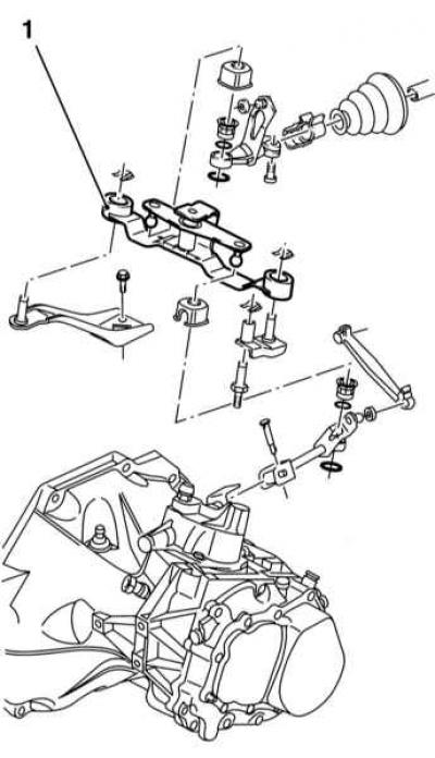
Scheme of installation of the drive rod assembly
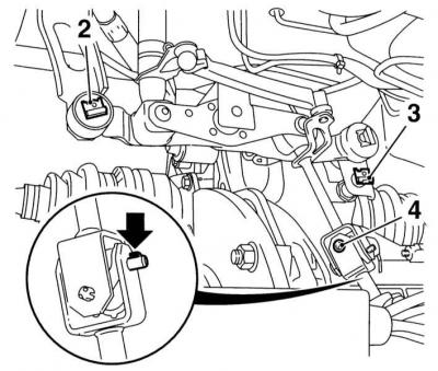
2 - Latch for fastening the assembly
3 - Latch for fastening the assembly
4 — Axis of fastening of draft of switching to the lever of a choice of transfers (on top of the gearbox crankcase)
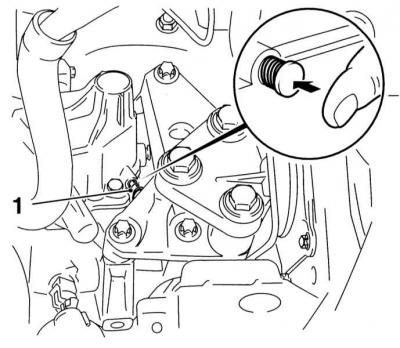
1. Disconnect the selection rod from the clamp - the bolt is located behind the power unit in front of the rear bulkhead of the engine compartment and on most models it can be accessed from above, otherwise you should jack up the front of the car and install (access to the bolt from below is very limited).
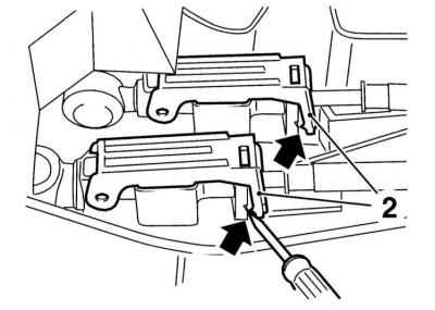
2. Release the clamps and remove the axle that connects the shift rod to the gear selection lever in the upper part of the manual transmission housing - the axle must be replaced without fail (see illustration Scheme of installation of the drive rod assembly).
3. Release the mounting of the support bracket, turn the rod assembly up and remove it from the vehicle. If necessary, the brackets can also be removed after releasing the fixing bolts.
4. Examine the linkage assembly for damage, replace failed components.
Models F23
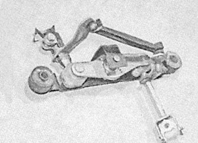
The design of the gearshift drive manual transmission F23
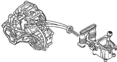
Elements of the shift drive mechanism (F23)
The assembly consists of a shift lever, drive cables of the linkage assembly (see illustrations The design of the gearshift drive manual transmission F23 and Elements of the shift drive mechanism (F23)).
Gear lever
1. Remove the center console (see chapter Body).
2. Prying with a small screwdriver, release the cable clamps, - press the clamps until they click.

Further pulling out the latches carries the risk of damaging them!
3. Note the fixed position of the cables, then separate their tips from the arm base.
4. Release the cable retainers at the front of the arm assembly.
5. Turn out four fixing bolts and remove assemblage of the lever of switching from a floor.
6. If necessary, the ends of the cables can be removed from the lever. The compilers of this Manual do not recommend further disassembly of the gear lever.
Drive cables
1. Remove the center console (see chapter Body).
2. Prying with a small screwdriver, release the cable clamps, - press the clamps until they click.
Further pulling out the latches carries the risk of damaging them!
3. Note the fixed position of the cables, then separate their tips from the arm base.
4. Release the front cable locks.
5. Remove the distribution duct.
6. Remove the battery (see chapter Engine electrical equipment).
7. Remember the fixed position of the cables, then separate their tips from the gearshift mechanism on the manual transmission housing.
8. Release the cable sheaths from the linkage support bracket.
9. Retract the cables into the engine compartment through the opening in the bulkhead.
Installation
Models F13, F17 and F18
Shift lever and selector rod
1. If disassembled, assemble the lever with the stem - make sure that the base of the lever is correctly installed on the axle.
2. Lubricate the axle and bearing surfaces with silicone grease and install the assembly in its proper place. Fit the fixing bolts, then tighten them to the required torque.
3. Install the switch panel, - follow the correct wiring. Reinstall the center console (see chapter Body).
4. Under the car, put a rubber boot on the gear selector rod shank and securely fix it on the bulkhead of the engine compartment.
5. Connect the stem shank with the tie rod collar, - make sure that the alignment marks applied during the dismantling process are aligned correctly. Tighten the clamp bolt to stage 1 torque, then tighten it to stage 2 corner (see Specifications).
6. Check the proper functioning of the gear shift mechanism, - if necessary, make the necessary adjustment (see Adjustment of a drive of a gear change), then lower the vehicle to the ground.
Drive rod assembly
You will need a new lever axle.
1. Before installation, lubricate the hinges and axle joints with silicone grease.
2. Install the assembly in its proper place and install the bracket on the supports. Secure the assembly in this position with the brackets, seating them in the grooves of the axles (see illustration Scheme of installation of the drive rod assembly).
3. Connect the rods to the lever and fill the new axle. Fix the axle securely with the retaining mechanism (see illustration Scheme of installation of the drive rod assembly).
4. Connect the stem shank with the tie rod clamp, - make sure that the alignment marks applied during the dismantling process are aligned correctly. Tighten the clamp bolt to stage 1 torque, then tighten it to stage 2 corner (see Specifications).
5. Check the proper operation of the gear shift mechanism, - if necessary, make the necessary adjustment (see Adjustment of a drive of a gear change), then lower the vehicle to the ground.
Models F23
Gear lever
1. If removed, connect the ends of the cables to the base of the lever - use pliers.
2. Install the lever assembly on the floor of the car, screw in the fixing bolts and tighten them with the required force.
3. Loosely install the front cable retainers.
4. Connect the ends of the cables to the arm base.
5. Adjust shift mechanism (see Adjustment of a drive of a gear change).
6. Reinstall the center console (see chapter Body).
Drive cables
1. Push the cables through the opening in the bulkhead of the engine compartment.
2. Fit the cable sheaths into the manual transmission housing bracket.
3. Connect the ends of the cables to the rods - use pliers.
4. Make sure that the cables are routed correctly, then, while not latching, install the cable sheath retainers into the receiving grooves.
5. Connect cable ends to arm base.
6. Adjust shift mechanism (see Adjustment of a drive of a gear change).
7. Install the air distribution duct and center console (see chapter Body).
Visitor comments