
Remember that the dust produced during the wear of the friction linings of the clutch disc may contain asbestos, which is harmful to health. Do not blow off dust with compressed air and try not to inhale it. Do not use petroleum-based solvents to clean clutch components, use only special brake cleaners or pure methanol. Store used rags in a sealed container.
Removing
In order to gain access to the clutch assembly, it is common to remove the transmission while leaving the engine on the vehicle. If the engine has already been removed for general or overhaul, the condition of the clutch components must be checked without fail. Given the relatively low cost of parts and the rather large amount of locksmith work to provide access to the clutch assembly, it makes sense to replace the latter, regardless of the condition of its components. Below is a description of the procedure for removing the clutch without removing the engine from the vehicle.
1. Remove the gearbox (see chapter Manual transmission), - support the engine with a jack, or hang it on top of the winch (preferably the latter). If using a jack, be sure to place a piece of wood between the jack head and the sump to distribute the load.
The oil pump intake is located very close to the bottom of the oil pan and can easily be damaged if the latter is deformed.
2. To prevent the driven disc from falling out when removing the basket, thread a tool designed to center the clutch into its hub.
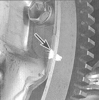
3. Carefully inspect the surfaces of the flywheel and clutch basket assembly for markings (usually in the form of letters X or O applied with white paint). If you cannot find the marking, apply it yourself, clearly marking the position of the basket relative to the flywheel.
4. Acting in a diagonal order, in several steps (half a turn per approach) evenly loosen the bolts securing the clutch basket to the flywheel, completely unloading the diaphragm spring - before releasing the bolts, the flywheel can be blocked using a special tool.
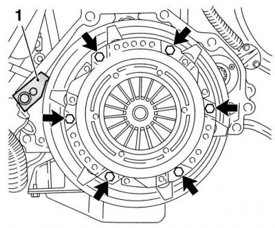
5. While firmly supporting the clutch assembly, finally remove the bolts, then separate the basket from the flywheel and remove the entire assembly from the vehicle.
6. Remove the friction disc - try to remember which side it is installed on the flywheel.
Examination
Assembly of the slave disk
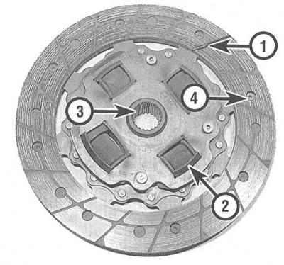
1 — friction linings in the picture worn below the allowable limit
2 — Torsion springs or dampers should be checked for cracks and signs of deformation
3 — Splined hub must slide freely on the splines of the input shaft of the gearbox, the splines must not be excessively worn
4 — Rivets are used to fasten friction linings and, if the latter are worn excessively, they begin to leave grooves on the working surface of the flywheel
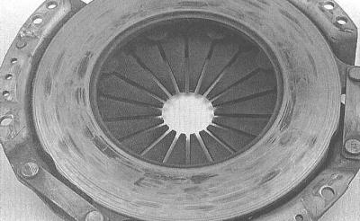
Examples of Diaphragm Spring Wear

Most often, a malfunction in the functioning of the clutch turns out to be associated with wear of the friction linings of the driven disk. However, you should carefully examine the status of all other assembly components.
1. Examine the working surface of the flywheel for cracks, traces of overheating, grooves and other damage. Minor defects can be eliminated by turning in the conditions of a car service workshop (the groove is recommended to be made regardless of the state of the surface). The description of procedures of removal and installation of a flywheel is given in the corresponding section of the Head Engine.
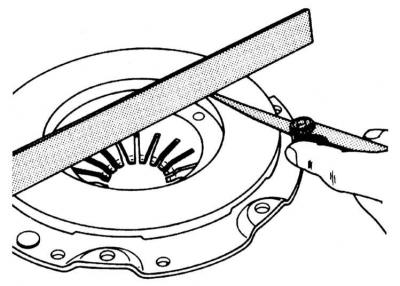
2. Also check the condition and evaluate the flatness of the mating surface of the clutch pressure plate.
3. Assess the degree of wear of the friction linings of the clutch driven disk. The surface of the overlays must rise above the heads of the rivets by at least 1.6 mm. Make sure that all rivets are firmly seated, check torsion springs / dampers for cracks, signs of deformation and other mechanical damage (see illustration Assembly of the slave disk). Lubrication of friction linings most often occurs due to failure of the crankshaft oil seal, violation of the integrity of the oil pan gasket, the sealing element of the slave cylinder assembly or the manual transmission input shaft oil seal, - replace the damaged components (see relevant chapters). As mentioned above, it is reasonable to replace clutch components every time the assembly is dismantled, so pay attention to the slightest errors.
4. Together with the driven disk, the release bearing is also always replaced. If the driven disk is in order, check the condition of the release bearing - the bearing should rotate smoothly, without signs of jamming. The mating surfaces must be absolutely smooth and undamaged, without cracks, burrs or gouges. If there is no certainty in determining the condition of the bearing, replace the slave cylinder assembly (see Removing and installing clutch slave cylinder assembly with release bearing).
5. Assess the condition of the machined surfaces and petals of the pressure plate diaphragm spring (see illustration Examples of Diaphragm Spring Wear). If defects are found, replace the basket assembly. Light polishing marks can be removed with fine sandpaper. You can always purchase a remanufactured clutch assembly on an exchange basis through Opel branded workshops.
Installation
1. Make sure that the mating surfaces of the flywheel and clutch discs are absolutely clean and dry, if necessary, wipe the working surfaces with a solvent.
2. Install the friction protruding part of the hub from the flywheel. Usually the disc is factory marked, indicating which side to the flywheel it should be installed («Flywheel side» or «Getriebeseite»).
3. Install the clutch basket - if an old basket is installed, make sure that the landing marks applied during the dismantling process are aligned correctly. Screw in the basket mounting bolts and tighten them only by hand so far in order to ensure the possibility of unhindered centering of the driven disk.
4. Now it is necessary to center the friction disc so that when the transmission is installed, its input shaft passes through the splines in the disc and enters the guide sleeve in the crankshaft trunnion.
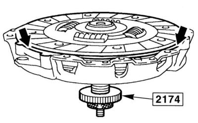
5. You can center the friction disc using a screwdriver, threaded through its central hole and inserted into the crankshaft guide sleeve. Significantly facilitates the task of using a special mandrel (attachment type No. 2174) in the form of a trunnion of the input shaft of the transmission. Good results are also achieved using a thin rod with electrical tape wound around it to the required diameter.
6. Having finished centering the driven disk, in several steps in a diagonal manner, evenly tighten the bolts securing the basket with the required force. Remove the centering tool.
7. Reinstall the gearbox (see chapter Manual transmission).
Visitor comments