
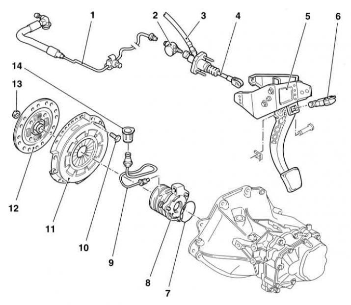
1 — Hydraulic line of a driving path of deenergizing of coupling
2 - Damper
3 — the Hose connecting the main cylinder with the tank
4 — a rod of a pusher of a main cylinder of coupling
5 - Clutch pedal bracket
6 - Sensor-switch of the position of the clutch pedal (models with tempostat)
7 - O-ring
8 - Assembling the clutch slave cylinder with release bearing
9 - Hydraulic line
10 — Bolt of fastening of a basket of coupling
11 - Assembling the clutch basket with the pressure plate
12 - Slave (friction) clutch disc
13 - Guide sleeve
14 - Union nut
All models equipped with a manual transmission use a single-disk, dry-type clutch with a diaphragm spring. Friction hub (slave) The disk is equipped with longitudinal splines that engage with the splines of the trunnion of the transmission input shaft. The friction and pressure plates of the clutch are held in contact with each other due to the force developed by the diaphragm spring of the pressure plate. The design of the clutch and its drive - see illustration The design of the clutch and its drive components.
The clutch is released hydraulically. The shutdown drive consists of a clutch pedal, a main hydraulic cylinder with a reservoir, connecting lines and an executive cylinder combined with a release bearing, planted directly on the input shaft of the gearbox (see illustration The design of the clutch and its drive components).
When the pedal is depressed, hydraulic pressure rises in the system path, which as a result is applied to the release bearing mounted in the slave cylinder. The bearing, under the influence of hydraulic force, is pressed against the petals of the diaphragm spring of the pressure plate in the clutch basket. Bending, the spring breaks the contact of the pressure and driven discs, releasing the latter.
When servicing a clutch, in addition to replacing components with obvious damage, some initial checks must be made (it is assumed that the gearbox is in good condition):
- The first step is to check the fluid level in the clutch master cylinder (see chapter Current service). If necessary, make adjustments by adding the required amount of hydraulic fluid and carefully inspect the system for signs of leaks. When emptying the reservoir of the master cylinder, it is necessary to remove air plugs from the hydraulic path (see Removal of air from the hydraulic path of the clutch release drive), then check that the clutch is working properly.
- Run the engine at normal idle to estimate clutch shift time. Make sure the gear is in neutral and release the clutch pedal. Now depress the clutch pedal and, after waiting a few seconds, engage reverse gear. Switching should not lead to the occurrence of rattle and other extraneous noise, with a high degree of probability indicating a malfunction of the driven disk or clutch basket assembly.
- To check that the clutch is fully disengaged, apply the parking brake and start the engine. While holding the clutch pedal about 13 mm above the floor, shift the transmission between first and reverse gears. The presence of interference when switching the lever indicates a malfunction of the components of the shutdown mechanism. Estimate a course of a pusher of the executive cylinder of coupling. With the pedal fully depressed, the pusher should move forward by a noticeable amount, otherwise the hydraulic fluid level in the master cylinder should be checked.
- Perform a visual check of the condition of the axle bushings at the top of the clutch pedal. Check for signs of jamming or excessive axle play.
Visitor comments