


Contents: Is there ignition voltage? ⬇ Visual inspection of the ignition…⬇ Checking the voltage supply to the…⬇ Sources of malfunctions ⬇ Checking the ignition coil ⬇ Checking the pulse sensor ⬇ Is it necessary to check the control…⬇
Anyone who wants to detect a defect in the ignition must act according to the system:
- A simple voltage test in the ignition system checks whether the ignition spark occurs at all.
- A precise visual inspection of the ignition system allows you to detect the most common causes of defects (wires, connectors, voltage surges, etc.).
- Only after this proceed to checking the ignition system components.
Is there ignition voltage?
Let's check from the very beginning whether a spark is formed in the ignition system at all:
Disconnect the spark plug connector and unscrew the spark plug.
Put the connector back on the spark plug and place it on the engine block so that it has a good ground connection and engine movements cannot throw it off. It is even better to connect the threaded part of the spark plug to the engine via an auxiliary jumper cable.
Have your assistant crank the engine with the starter.
If powerful sparks jump across the spark plug electrodes, then there is ignition current and, most likely, the ignition system is in order.
However, there may be defects that are not detected in this way: a faulty sensor or incorrect calculation of the ignition timing by the control unit.
If there is no spark, take a spark plug from another cylinder. If there is still no spark, then you need to check the entire ignition system as a whole.
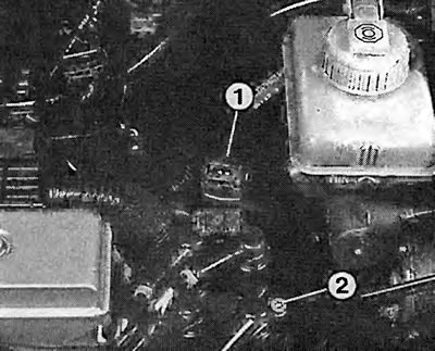
Ignition stop: With the ignition off, disconnect the connector "1" at the rear of the DIS ignition module "2".

Is there ignition voltage? Place the spark plug with the connector on the engine so that it has reliable contact with the ground. Have your assistant turn the engine with the starter. If powerful sparks jump on the spark plug electrode, then there is ignition current.
Visual inspection of the ignition system
Are all wire connectors and plug contacts securely connected to the DIS ignition module and to the ignition/injection control unit?
Could it be that a single contact in the multi-pin connector on the control unit has become disconnected?
Has the DIS ignition module leaked filler material? Then the module is probably faulty.
Are there any cracks or burn marks from sparks on the DIS ignition module housing?
Additionally, check the main ignition wire for tight connections and insulation damage. Modern ignition systems are particularly sensitive to spark breakdown and leakage currents due to high voltages.
Are all ignition system components clean and dry? Wet dirt can cause voltage breakdown.
Tip: When taking the following measurements, ensure that the measuring and control devices are connected and disconnected only when the ignition is switched off.
Checking the voltage supply to the ignition system
Along with the complete failure of the ignition system due to lack of voltage, insufficient voltage can also lead to significant disruptions in the operation of the system! Therefore, it is better to use a voltmeter here. Test condition: charged battery.
Disconnect the connector behind the DIS ignition module.
For 1.8L and 2.0L engines, connect the measuring device to the disconnected connector between terminal "3" and engine ground.
In Vectra with 1.6L engine, connect the measuring device to the disconnected wire connector between contact "1" (positive) and contact "2" (ground).
For everyone: turn on the ignition.
At least 11.5V should be read.
If the device does not show voltage at all or shows too low voltage, then the defect lies in the wire to the ignition switch.
[Article posted on an online resource: opelbook]
Sources of malfunctions
The ignition switch is faulty (chapter "Tools and instruments").
There is no continuity in the supply wire from the ignition switch to the DIS ignition module or to the control unit. Check the entire length of the wires and connectors using the electrical diagram in this book.
Checking the ignition coil
First, check to see if the spark plugs are sparking. If so, the DIS ignition module is probably OK.
If not, check the voltage supply as described. If there is voltage but no spark: check the ignition pulses (moving from the control unit) as described below.
There is voltage and ignition pulses are received, but there is no spark: then the DIS ignition module is faulty.
A visual check of the DIS ignition module has already been carried out.
Checking the ignition pulses: Disconnect the connector on the DIS ignition module at the rear.
Connect the LED voltage indicator to contacts "1" and "3" of the disconnected connector.
Have your assistant operate the starter: the voltage indicator should flash.
Perform the same test on 1.6L vehicles between terminals "1" and "4" and on 1.8L and 2.0L vehicles between terminals "2" and "3". The voltage indicator should also flash during this test.
If the LED is flickering, then ignition pulses are coming to the module. If the ignition is not working, only the DIS ignition module may be defective.
If there are no pulses, the problem is in the control unit, in the supply wire, or in the voltage supply to the control unit.
Checking the pulse sensor
The sensor is located in the direction of travel on the left in the engine compartment behind the crankshaft belt pulley. The connection of its wire plugs is made from the right side up, so there is no need to measure the voltage under the car.
Trace the transmitter wire to the wiring harness, check the plug connections and wires.
Disconnect the pulse sensor connector in the engine compartment.
Connect the measuring device to the sensor wire.
Operate the starter: the meter should read more than 1V between terminal 1 and terminal 2.
If the voltage value is OK, unscrew the pulse sensor from the engine block.
Clean the end face of the pulse sensor. Dirt or grease in this area will interfere with its operation.
Check the air gap between the sensor/ring gear with a template.
The distance should be 0.1-1.5 mm.
The workshop also has the additional option of observing the sensor voltage curve on the monitor.
Is it necessary to check the control unit yourself?
The ignition/injection control unit is on the left: in the relay box in the engine compartment. The amateur's art ends with checking the control unit. The risk of causing damage due to an error when connecting to the connector is too great. And a new control unit is not cheap.
In addition, the probability that the cause of ignition failure lies in the control unit is estimated as insignificant.
Most often, the source of the malfunction lies in other units of the ignition system. Damaged wires or loose connectors are found by visual inspection. There is still the ignition coil or high-voltage unit to check, as well as the Hall sensor or inductive pulse sensor. If nothing is found after the above checks, it is best to send the car to an Opel or Bosch workshop. Ignition system malfunctions will be found much faster with a suitable device in the workshop than an amateur can do.
Visitor comments