
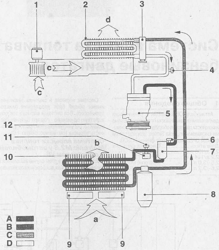
14.0 Schematic diagram of the air conditioner
1 - fan
2 - evaporator
3 - throttle valve
4 - connecting pipe for low pressure supply during service work
5 - compressor
6 - connecting branch pipe for supplying high pressure during service work
7 - dryer
8 - dryer filter
9 - fan. Vehicles with a 6-cylinder petrol engine and a turbocharged diesel engine have two fans
a - air flow when the car is moving, cooling radiator
b - hot air
c - uncooled air supplied by the fan
d - cooled air supplied to the passenger compartment
A - high blood pressure (gaseous refrigerant)
B - high pressure (liquid refrigerant)
C - low pressure (liquid refrigerant)
D - low pressure (gaseous refrigerant)
The air conditioning compressor is driven by a ribbed belt from the engine crankshaft. The compressor pressurizes the refrigerant circuit up to a maximum of 30 bar, which heats up the refrigerant and changes it into a gaseous state. The radiator takes heat from the passing hot air (cold air stays outside), which leads to cooling of the heated refrigerant and it returns to the liquid state (condenses). Flowing further along the circulation circuit under pressure, the refrigerant passes through a throttle valve, which reduces the pressure. After passing through the throttle, the refrigerant enters the evaporator and is re-cooled there. The cold refrigerant takes heat from the hot air around the evaporator, thereby cooling it. This cooled air is fed into the passenger compartment.
From the heat received, the refrigerant becomes gaseous again and, under the influence of low pressure, is supplied to the compressor and the circulation of the refrigerant is repeated.
Attention! The order of work relating to the repair of the air conditioner in this manual is not given. Repair of the air conditioner must be carried out by a specialized workshop. Please note that the refrigerant circuit in the air conditioner must not be opened. Skin contact with refrigerant may cause frostbite.
Visitor comments