
General information and device
The air intake for interior heating occurs through the air intake grille with an anti-dust filter, located under the windshield. Outside air passes through the dust filter (air cleaner) and enters the fan casing, and from there - into the heater radiator, from where, already in a heated state, through the air distribution dampers it enters the deflectors in the cabin.
Depending on the position of the heater regulator, a larger or smaller amount of outside air is drawn through the heater core. The heater core is located inside the heater housing and is heated by hot coolant flowing through the heater. The air heated in the heater radiator is supplied to the passenger compartment. The temperature of the air supplied to the passenger compartment is controlled by mixing fresh outside air and heated air in the heater using an air distribution damper.
A fan is installed to increase the volume of air supplied for interior heating. The fan can work with different intensity (speed), which is provided by the appropriate resistors installed on the fan connection board. In the event of a malfunction, the board is replaced as a set (see illustration 9.0, 9.0a and 9.0b).
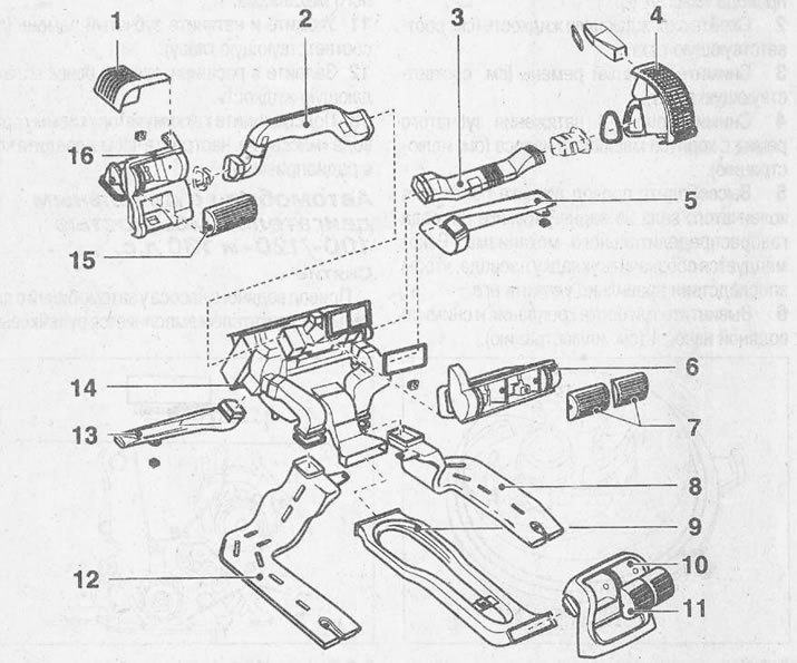
9.0 Cooling system components
1 - side window deflector
2 - air channel of the cabin air deflector on the driver's side
3 - air channel of the cabin air deflector on the passenger side
4 - cabin air deflector on the passenger side
5 - air duct and air deflector for the footwell on the passenger side
6 - housing of central deflectors
7 - grids of central deflectors
8 - air channel of the air deflector of the rear right side of the passenger compartment
9 - lower part of the center console
10 - housing of grilles of air vents for blowing the rear part of the cabin
11 - lattice deflectors blowing the rear of the cabin
12 - air duct rear deflectors
13 - air duct of the deflector for blowing the niche for the legs on the driver's side
14 - body of air distribution dampers
15 - side deflector
16 - side deflector body
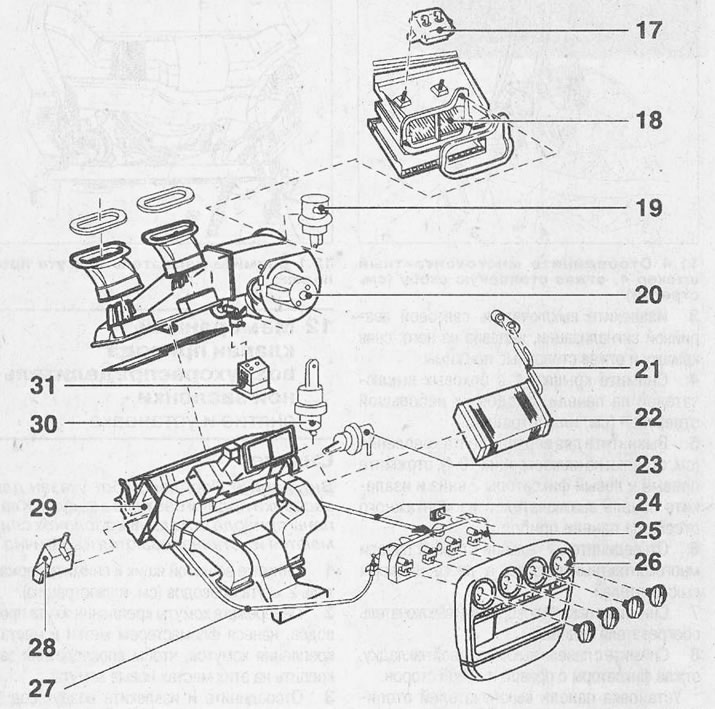
9.0a Cooling system components
17 - vacuum receiver
18 - air cleaning filter
19 - diaphragm damper damper fresh air
20 - fan motor
21 - heater pipelines
22 - heater
23 - fresh air damper diaphragm valve
24 - temperature control cable on the front passenger side. The cable can only be removed after the instrument panel has been removed.
25 - heater switch panel
26 - switch panel overlay
27 - temperature control cable on the driver's side. Dismantling the cable is only possible after removing the instrument panel
28 - fresh air damper solenoid valve
29 - distribution damper housing
30 - defroster damper diaphragm valve
31 - resistor board for blowing the cabin fan
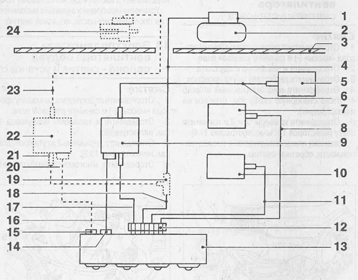
9.06 Air damper drive
1 - branch pipe for fastening the low pressure hose from the intake manifold
2 - vacuum receiver
3 - partition of the engine compartment
4 - yellow low pressure hose
5 - membrane damper damper fresh air
6 - blue low pressure hose
7 - membrane valve of the defroster damper
8 - brown low pressure hose
9 - fresh air damper solenoid valve
10 - membrane valve of the damper of the airflow deflector of the footwell
11 - yellow low pressure hose
12 - connecting branch pipe of low pressure hoses
13 - heater switch panel
14 - switch for air recirculation mode in the cabin
15 - microcontact switch
16 - wiring harness with blue, white and brown insulation
17 - blue low pressure hose
18 - yellow low pressure hose
Only for vehicles with air conditioning
19 - T-piece
20 - wiring harness with yellow, black and brown insulation
21 - black low pressure hose
22 - shut-off valve solenoid valve
23 - black low pressure hose
24 - heater shut-off valve
Visitor comments