


Warning: Be careful not to allow dirt to enter the fuel pump.
When installing the cylinder head, upper guides and camshaft sprocket, new bolts must be used.
Removal
1. Drain the coolant from the cooling system.
2. Remove the ground cable from the battery and the cylinder head cover.
3. Remove the brake vacuum pump.
4. Set the piston of the first cylinder at the top dead center in the compression stroke and fix the crankshaft.
5. To improve access to the fuel pump sprocket cover, follow these steps:
- remove the air filter housing and front exhaust pipe;
- remove the auxiliary drive belt;
- unscrew the mounting nut from the powertrain suspension frame and lift the engine just enough to avoid deforming the hoses and pipes.
6. Remove the upper chain tensioner.
7. Remove the drive belt tensioner mechanism.
8. Remove the bolts and remove the fuel pump sprocket cover.
9. Make alignment marks between the top chain and sprockets, and between the camshaft sprocket and camshaft.
Article published on the website [www.OpelBook.ru]
10. Unscrew the bolts and remove the upper chain guide.
11. Before unscrewing the upper chain guide mounting bolts, the bolts must be heated to soften the compound that prevents the bolts from unscrewing.
12. Using a wrench, secure the camshaft from turning and unscrew the camshaft sprocket mounting bolts. Before unscrewing the bolt, remove the crankshaft locking pin and after unscrewing the bolt, install the pin in place.
13. Remove the chain from the camshaft sprocket and remove the sprocket from the engine. Place a screwdriver or steel rod under the chain to prevent it from falling into the cylinder head.
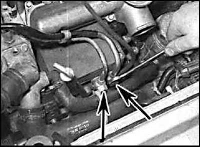
14. Clean the area around the fuel supply line connection to the fuel pump and remove the line mounting bolts.
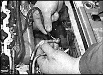
15. Disconnect the return line from the fuel pump. Disconnect the lines from the mounting brackets and move them away from the cylinder head.
16. Remove the intake and exhaust manifolds. If disassembly of the cylinder head is not required, it can be removed together with the manifolds after performing the following steps:
- on turbo models, disconnect the intake ports and metal pipe from the turbocharger,
- unscrew the bolt securing the wiring harness to the top of the intake manifold and disconnect the electrical connectors,
- disconnect the electrical connector from the crankshaft sensor,
- disconnect the pipes from the fuel injectors,
- disconnect the vacuum hoses from the intake manifold switch and EGR valve,
- disconnect the electrical wires from the glow plugs and remove the turbocharger heat shield,
- disconnect the turbocharger oil lines from the cylinder block, disconnect the throttle diaphragm vacuum hose,
- remove the starter heat shield.
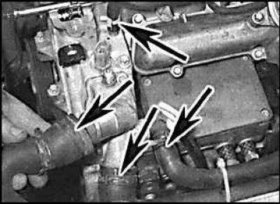
17. Loosen the clamps and disconnect the coolant supply hoses (indicated by arrows) to the cylinder head.
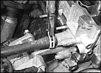
18. Remove the coolant supply hoses to the rear of the cylinder head.
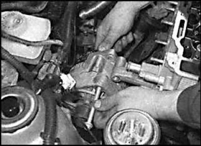
19. Remove the upper alternator mounting bolt and move the alternator away from the cylinder head.
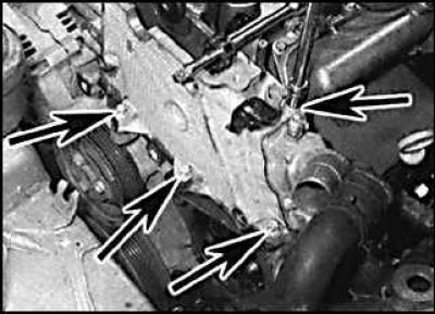
20. Remove the three bolts securing the right end of the cylinder head to the top of the chain cover and one bolt securing the cylinder head to the cylinder block (indicated by arrows).
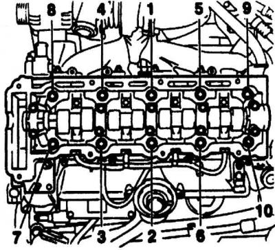
21. Gradually and sequentially in the order shown in the figure Cylinder head bolt tightening sequence unscrew 10 cylinder head mounting bolts.
22. Remove the cylinder head mounting bolts together with the washers.
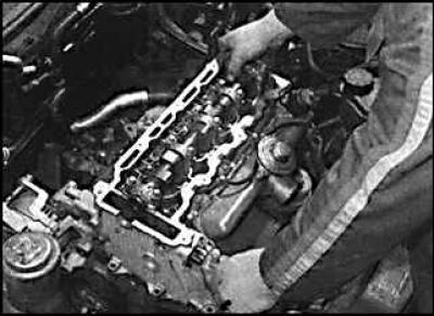
23. Remove the cylinder head.
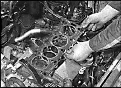
24. Remove the cylinder head gasket.
Warning! Do not place the cylinder head bottom on a table, but only on wooden blocks, as the fuel injectors and glow plugs protrude from the cylinder head.
Preparing for installation
1. The mating surfaces of the engine head and cylinder block must be thoroughly cleaned of gasket residue and carbon deposits using a plastic or wooden scraper. It is also necessary to clean the upper parts of the pistons. When cleaning, eliminate the possibility of cleaning products getting into the oil channels of the cooling system. Thoroughly clean the inner surfaces of the cylinders.
2. Check the mating surfaces of the engine head and cylinder block for defects. Minor damage can be repaired by mechanical treatment. Also, using a metal ruler and feeler gauge, check the flatness of the mating surfaces.
3. Clean the bolt holes in the block. Driving a bolt into an oil filled hole can cause the block to burst due to hydraulic pressure.
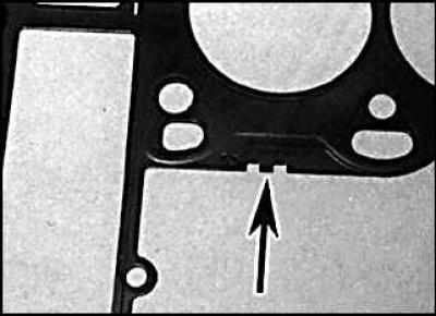
4. Depending on the amount of piston protrusion from the cylinder block, it is necessary to use a head gasket of a strictly defined thickness. The thickness of the gasket is identified by holes punched in the left front corner of the gasket. The cylinder head thickness identification mark is indicated by an arrow.
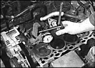
5. Check that the crankshaft is at the top dead center of the piston of the first cylinder. Mount a dial indicator on a bracket on the cylinder block. Mount the measuring tip on the cylinder block and set the dial indicator scale to 0. Mount the measuring tip on the piston of the first cylinder and turn the crankshaft slightly in both directions and note the highest value on the indicator. Record this value.
6. Measure the piston protrusion on cylinder No.4 in the same way. Then turn the camshaft 180° and repeat the piston protrusion measurement on cylinders 2 and 3. Turn the camshaft 540° and set it to its original position.
7. Using the maximum piston protrusion value, select the cylinder head gasket.
|
Number of holes
|
Gasket thickness
|
|
No hole
|
1.20 mm
|
|
1 hole
|
1.30 mm
|
|
2 holes
|
1.40 mm
|
|
3 holes
|
1.50 mm
|
|
Piston protrusion
|
Gasket thickness
|
|
0.40 – 0.50 mm
|
1.20 mm
|
|
0.51 – 0.60 mm
|
1.30 mm
|
|
0.61 – 0.70 mm
|
1.40 mm
|
Installation
1. Wipe the mating surfaces of the cylinder block and cylinder head.
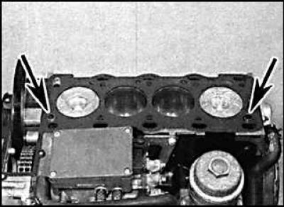
2. Check that the two guide pins (indicated by arrows) installed in the cylinder head and install the cylinder head gasket.
3. Check that the crankshaft is fixed in the position of the top dead center of the piston of the first cylinder in the compression stroke, and the camshaft cams of the first cylinder are directed upward and the groove on the left side of the camshaft is parallel to the surface of the cylinder head.
4. Install the cylinder head. Remove the upper chain to the top of the cylinder head and secure it to the head using a screwdriver blade or steel rod.
5. Lubricate the cylinder head mounting bolts with engine oil, insert them into the head and tighten by hand.
6. Gradually and sequentially tighten the cylinder head mounting bolts in several stages (see figure Cylinder head bolt tightening sequence).
7. Tighten the chain cover mounting bolts to the right side of the cylinder head.
8. Rotate the generator towards the engine and secure the upper generator mounting bolt.
9. Connect the cylinder head coolant supply hoses and secure them with clamps.
10. Install the intake and exhaust manifolds.
11. Install the camshaft sprocket onto the camshaft.
12. Install the fuel supply lines with new washers and tighten them to the specified torque.
13. Fill the engine cooling system with coolant.
Visitor comments