
Depending on the direction of torque supply to the friction clutch, the discs can be driven or driven.
Part of the discs is fixed on the splines of the clutch hub, other discs are mounted on the splined surfaces of the drum or gearbox housing. When the hydraulic piston moves away from the clutch. its hub, together with the disks, rotates freely relative to the drum or gearbox housing. When pressure is applied to the rear surface of the piston, the piston presses the driven and driven discs together, causing the hub to rotate with the clutch drum or remain in contact with the gearbox housing. The clutch disengages when oil pressure drops on the back of the piston. Under the action of the return springs, the piston returns to its original position, while releasing the driven and driving discs.
The forward clutch consists of a housing welded to the input shaft, steel discs and discs with friction linings. sliding on the internal input gear. The hydraulic piston presses the discs against each other. The clutch is disengaged when the oil pressure drops behind the hydraulic piston. Under the action of the return springs, the piston returns to its original position, while releasing the driven and driving discs. When oil pressure is applied to the rear surface of the piston, the clutch is engaged and the internal input gear is connected to the input planetary gear. This clutch remains engaged in all forward gears.
When in neutral «N» the automatic transmission selector lever, the forward clutch is in the disengaged position.
The direct transmission clutch consists of a piston located in the housing, a ring with pressure and expansion springs, steel discs and discs with friction linings. This clutch is used to engage 2nd gear and reverse gear.
The 1st gear and reverse clutch is used to engage one of these gears. It consists of a piston, expansion spring, steel discs and discs with friction linings.
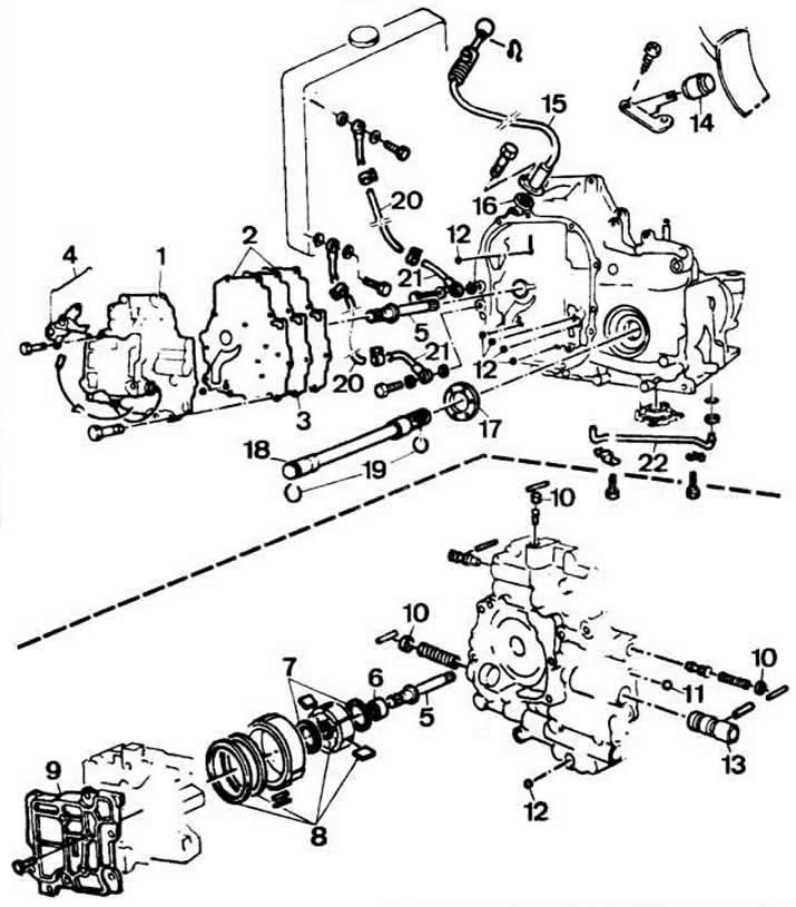
Details of the valve box, oil pump and forced reverse shift mechanism:
1 - body of the valve box-oil pump assembly;
2 - gaskets;
3 - shield;
4 - forced reverse switching mechanism;
5 - oil pump drive roller;
6 - bearing;
7 - sealing rings;
8 - details of the oil pump;
9 - cover of the oil pump;
10 - cork;
11 - ball with a diameter of 9.5 mm;
12 - balls with a diameter of 6.3 mm;
13 - sleeve;
14 - stop forced reverse switching;
15 - cable forced reverse switching;
16 - stuffing box;
17 - sealing ring;
18 - output shaft;
19 - retaining rings;
20 - pipeline for the removal and supply of oil to the cooler;
21 - fitting oil pipelines;
22 - drain pipeline.
Visitor comments