
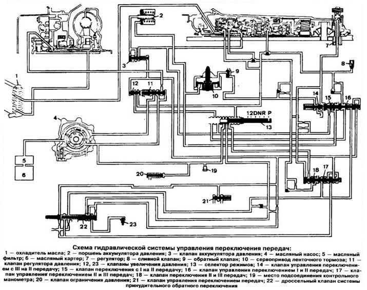
Schematic diagram of the hydraulic shift control system:
1 - oil cooler;
2 - pressure accumulator piston;
3 - pressure accumulator valve;
4 - oil pump;
5 - oil filter;
6 - oil sump;
7 - regulator;
8 - drain valve;
9 - check valve;
10 — band brake servo drive;
11 - pressure regulator valve;
12, 23 - pressure increase valves;
13 - mode selector;
14 - control valve for switching from III to II gear;
15 - switching valve from I to II gear;
16 - control valve for switching I and II gears;
17 - control valve for shifting II and III gears;
18 - valve switching II and III gears;
19 - the place of connection of the control pressure gauge;
20 - pressure limiting valve;
21 - gear shift control valve;
22 - throttle valve of the forced reverse switching system.
Visitor comments