
Removing
Attention! Before removing the front axle housing, it is necessary to ensure that the engine damping blocks are correctly fastened.
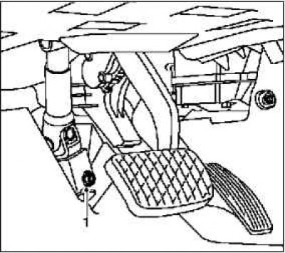
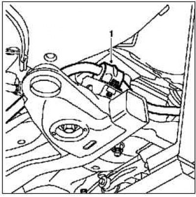
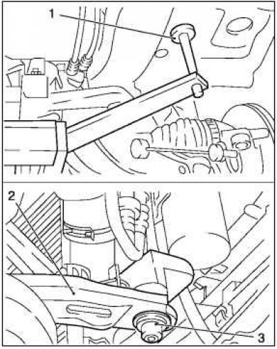
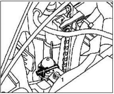
Before removing the intermediate steering shaft 1 from the small gear or steering shaft, set the steering to the straight-ahead position and lock the steering wheel shaft lock.
Remove the lower clamping screw 1 of the intermediate steering spindle from the steering gear.
Remove the steering intermediate spindle from the steering gear.
Attach the cooling module.
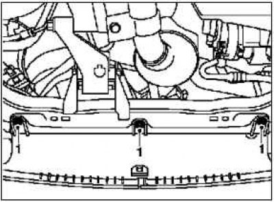
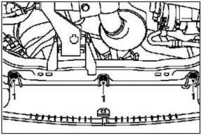
Fasten the tightening strap 1 in the upper holders.
Loosen the front axle housing trim.
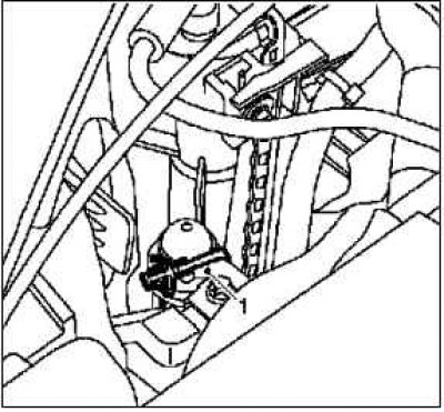
Remove plastic rivet 1.
If equipped: Remove the right engine mudguard.
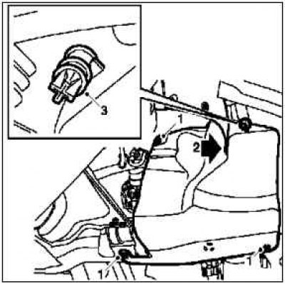
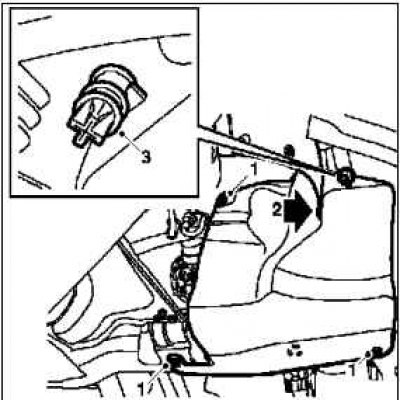
Remove screw 1.
Remove plastic rivet 2.
Unclip drain hose 3.
On the Corsa-C ECO model: remove the engine compartment cover I.
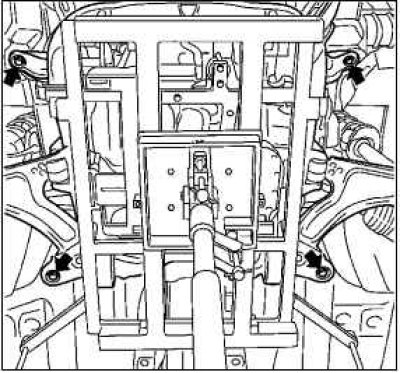
Note. Make sure that the guide pins of tool KM-6168-50 (arrows) sat on both sides in the guide holes of the bridge body.
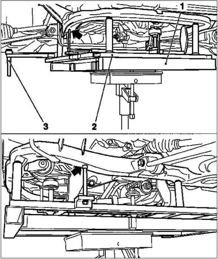
Mount tool KM-904 1 together with KM-6168-A 2 on a hydraulic jack and install without gaps under the front axle housing.
Note. To remove the front axle housing, first lower the dowel pins 3 on the KM-6168-A tool 2 on the bottom of the vehicle.
Remove the front axle housing.
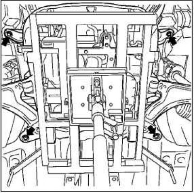
Remove 4 screws (arrows).
Lower the front axle housing with a 30 mm hydraulic jack.
Remove the stabilizer.
Mark the position of the stabilizer in relation to the front axle housing.
Remove the 2 bearing brackets 1 on the front axle housing.
Installation
Lubricate new stabilizer bearings.
Note. Before installation, lubricate the internal surfaces of the stabilizer bearings with special grease.
Note. Ensure that the stabilizer bearing holes are facing forward before installation.
Install stabilizer.
Place the stabilizer in the marked location on the front axle housing.
Install 2 bearing brackets 1 on the front axle housing 20 Nm.
Note. Make sure that the fixing pins of the radiator 3 are seated in the holders 2 on the front axle housing, and the locating pins 1 of the KM-6168-A tool are included in the mounting holes provided for this on the bottom of the vehicle.
Install the front axle housing.
Carefully jack the front axle housing from KM-6394 to KM-6168-A and KM-904 to the underside of the vehicle, the rear torsion bar holder, or the front torsion bar.
Drive the steering gear into the hole in the end wall.
Attach the front axle housing.
Tighten new screw (arrows) 90 Nm + 45°+ 15°.
Pull out the hydraulic jack.
Attach the front trim to the front axle housing.
Install clip 1.
If equipped: Install the right engine mudguard.
Tighten screw 1.
Install plastic rivet 2.
Clamp the drain hose 3.
On the Corsa-C ECO model: fit the engine compartment cover I.
Remove the drawstring 1 for attaching the cooling module.
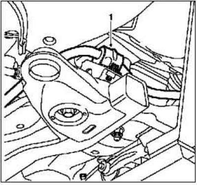
Install the steering intermediate spindle to the steering gear.
Note. The cardan joint should be easy to put on by hand.
Tighten new screw 1.
Replacing the hydraulic bushing of the independent suspension arm
Note. Control arm hydraulic bushings should always be replaced in pairs.
Removing
Remove the independent suspension arm.
Remove the hydraulic bushing from the control arm.
Drill out the rivet heads 1 - 10 mm in diameter.
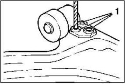
Paint the holes on the control arm with anti-corrosion paint.
Installation
Note. The new hydraulic bushing is threaded to the independent suspension arm.
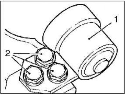
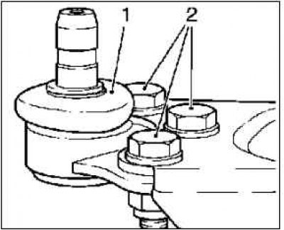
Install the new hydraulic bushing 1 on the upper side of the control arm with the special screws 2.
Insert 3 special screws 3 from top to bottom into the hydraulic bushing and control arm.
Tighten the 3 special screws 55 Nm.
Install the independent suspension arm.
Independent suspension arm pivot replacement
Removing
Remove the independent suspension arm.
Remove the control pivot from the control arm.
Drill out 3 heads of rivets 1 - 10 mm in diameter.
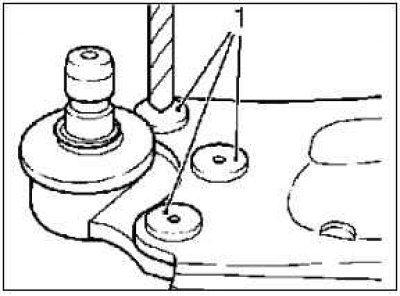
Paint the 3 holes on the control arm with anti-corrosion paint.
Installation
Note. The new pivot point is threaded to the independent suspension arm using special service compartment screws.
Install the new control joint 1 on the lower side of the control arm with the special screws.
Insert 3 special screws 2 from top to bottom into the control arm and control joint
Tighten the 3 special screws 55 Nm.
Install the control arm I.
Visitor comments