


Noises and knocks in the steering while driving
The cause of the malfunction may be too much play in the steering gear bearing bushing.
Troubleshooting
If a malfunction occurs, install the steering gear repair kit.
To replace the bushing, it is necessary to prepare a mounting bracket for the steering gear.
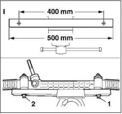
Note: The construction of the mounting bracket is described in steps 1–4.
1. Cut a 40x40 mm square steel pipe 500 mm long.
2. Drill 2 holes with a diameter of 12.5 mm.
The distance between the hole centers is 400 mm.
3. Fasten the steering mechanism to the square pipe with 2 M12x130 screws (1, 2).
Use washers and nuts.
4. Spot weld the screw heads (1, 2).
5. Remove the front wheels.
6. Hang the radiator on the air deflector.
Use 2 cable ties.
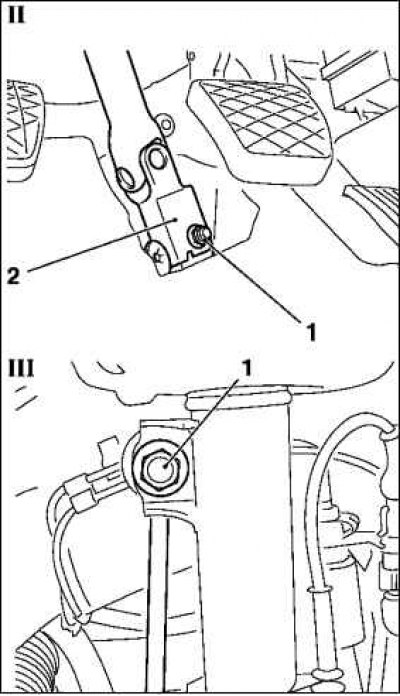
7. Disconnect the intermediate steering shaft 2 from the steering gear (figure II).
Unscrew and remove bolt 1.
8. Disconnect the 2 swing arms 1 from the shock absorber support tube (figure III).
Hold the two flats on the steering knuckle bolt with an open-end wrench.
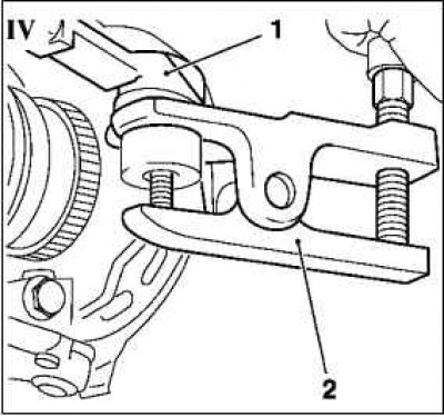
9. Disconnect 2 tie rod ends 1 using tool KM-507-C 2 from steering knuckles (figure IV).
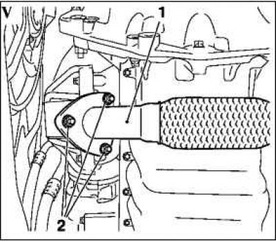
10. Remove the front exhaust pipe 1 from the catalytic converter (figure V).
Unscrew 3 nuts 2.
11. Remove the rear torque rod shock absorber block.
Unscrew the screw.
12. Disconnect the exhaust system.
Remove 2 rubber hangers.
Note: Secure the exhaust system to the underbody using suitable means.
13. Disconnect the oxygen sensor wiring harness connector.
14. Disconnect the front bumper from the axle housing.
Remove 3 plastic rivets.
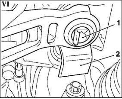
15. Disconnect the shift mechanism (figure VI).
Remove the retaining clip 1 from the shift mechanism 2.
Unhook the shift mechanism from the shift mechanism bracket at the top.
16. Install a hydraulic jack under the front axle housing together with the KM-904 and KM-6168 devices.
Note: Make sure the KM-6168 guide pins are inserted into the guide holes on both sides of the front axle housing.
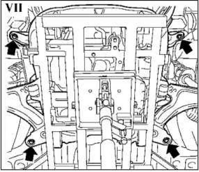
17. Unscrew the 4 screws on the front axle housing (figure VII, arrows).
18. Using a hydraulic jack, lower the front axle housing until the steering gear screws are accessible.
Note: Be careful not to lift the front axle housing off the KM-6168.
19. Remove the steering gear from the front axle housing.
Unscrew 2 screws.
Remove the steering gear.
20. Install the steering gear onto the prepared mounting bracket (see figure I).
21. Remove 2 anthers.
Remove 4 clamps.
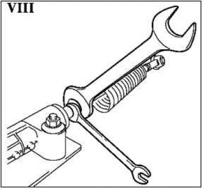
22. Remove 2 tie rods (figure VIII).
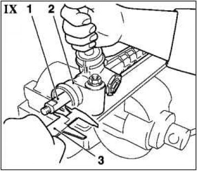
23. Set the steering gear to the middle position (figure IX).
Note: Measure the protrusion of both ends of steering shaft 1 relative to housing 2 using calipers 3.
The size should be the same on both sides.
The rack protrusion can be adjusted by turning the steering shaft.
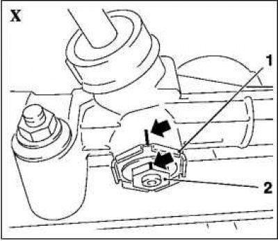
24. Apply marks (drawing X, arrows) on the body relative to the lock nut 1 and adjusting screw 2.
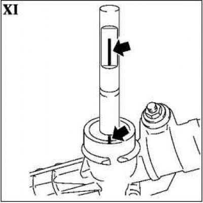
25. Apply marks (figure XI, arrows) on the body relative to the steering shaft.
26. Release the locknut (figure XII).
Use the KM-280 2 fixture.
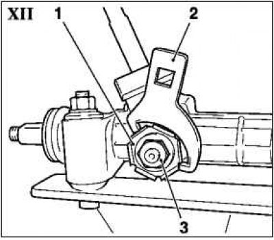
27 Loosen adjusting screw 3.
Note: The position of the lock nut relative to the adjusting screw must not be changed. This is necessary to ensure the correct mounting position.
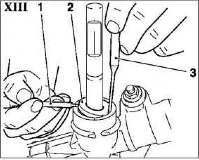
28. Remove the sealing ring (figure XIII, 2).
Use a suitable tool 3 to press the sealing ring into the housing.
Remove the sealing ring from the housing using screwdriver 1 as a lever.
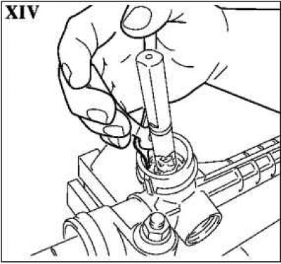
29. Remove the retaining ring (figure XIV).
Remove grease.
Remove the retaining ring.
30. Remove the steering shaft from the housing.
31. Remove the rack from the housing and check the surface.
Note: If the surface is damaged, such as grooves, the steering gear must be replaced.
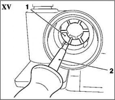
32. Remove the old bearing sleeve (figure XV).
Release bearing sleeve 1 using a suitable tool 2.
Push the bearing sleeve out of the housing from the opposite side using a long tool.
33. Clean the bearing seat.
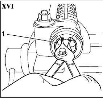
34. Install a new bearing sleeve (figure XVI).
Insert the bearing sleeve until it stops.
Install retaining ring 1.
35. Lightly lubricate the bearing sleeve with the supplied grease.
36. Install the toothed rack.
Lubricate the rack evenly with the supplied grease.
Insert the rack into the center of the housing.
37. Install the steering shaft.
Note: The rack must be set to the middle position.
The marks on the steering shaft and housing must match (see figure XI).
Measure the protrusion of both ends of the steering rack relative to the housing using a caliper.
Note: The size must be the same on both sides.
If the protrusion is not the same, repeat the operation to obtain the desired result.
38. Install the retaining ring.
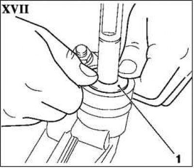
39. Install a new sealing ring (1, figure XVII).
Place the supplied grease into the housing.
Press the sealing ring in with your fingers.
40. Screw in the adjusting screw with the lock nut.
Note: The position of the lock nut relative to the adjusting screw must not be changed.
41. Tighten the lock nut to 80 Nm. The marks on the housing and on the adjusting screw must match.
Note: If necessary, hold the adjusting screw. Be sure to observe the adjustment marks.
42. Install 2 tie rods.
Apply locking compound to the pinion shaft threads.
Tighten the 2 tie rod ends (tightening torque 70 Nm).
Note: Hold the open-end wrench by the flats on the rack.
43. Install 2 anthers.
Install 4 clamps.
44. Remove the steering gear from the mounting bracket.
Unscrew 2 nuts.
45. Attach the steering gear to the front axle housing.
Insert 2 new bolts.
Use 2 new washers.
Tighten 2 new nuts to 45 Nm + 45° + 15°.
46. Install the front axle housing.
Using a hydraulic jack, carefully raise the front axle housing with the KM-6394 to KM-6168-A and KM-904 attachments to the vehicle underbody, rear torque rod bracket or front torque rod.
47. Secure the front axle housing.
Tighten 4 new screws to 90 Nm + 45° + 15°.
48. Attach the shift mechanism.
Insert the shift mechanism into the shift mechanism bracket from above.
Install the mounting clamp.
49. Attach the front bumper to the front axle housing.
Insert 3 plastic rivets.
50. Connect the oxygen sensor wiring harness connector.
51. Connect the exhaust system.
Install 2 rubber hangers.
52. Install the front torque rod shock absorber block.
Tighten the screw to a torque of 60 Nm.
53. Connect the front exhaust pipe to the catalytic converter.
Tighten the 3 nuts to 25 Nm.
54. Attach the 2 tie rod ends to the steering knuckle.
Tighten the new nuts to 35 Nm.
55. Attach the 2 swing arms to the shock absorber support tube.
Tighten the nuts to 65 Nm.
Hold the two flats on the steering knuckle bolt with an open-end wrench.
56. Attach the intermediate steering shaft to the steering gear.
Material taken from an internet portal [opelbook.ru]
Tighten the nut on the clamp bolt to 24 N·m.
57. Remove the radiator hanger to the air deflector.
Cut 2 plastic cable ties.
58. Install the front wheels.
Visitor comments