


General information
System type - 12V with negative grounding
Fuses and relays
|
Colour identification of fuses by rated current |
|
|
Red
|
10A
|
|
Blue
|
15A
|
|
Yellow
|
20A
|
|
Green
|
30A
|
|
Orange
|
40A
|
|
Red (maxi)
|
50A
|
Fuses and relays in the engine compartment on the left
The relay and fuse box is located on the left side of the engine compartment of models before 1994.
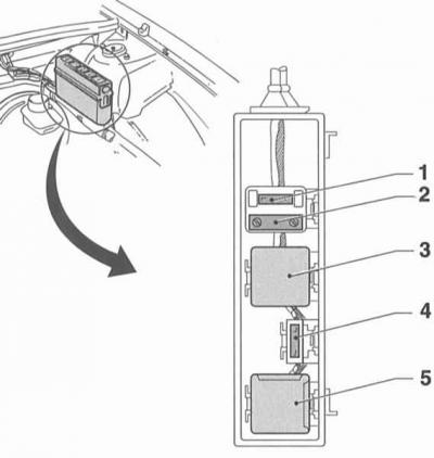
|
№ |
Purpose |
|
1
|
Diesel Engine Fuel Filter Preheater Fuse
|
|
2
|
Diesel Engine Glow Plug Fuse
|
|
3 |
Diesel engine fuel filter heating relay |
|
4
|
Horn and anti-theft alarm system fuse
|
|
5
|
A/C compressor relay
|
Mounting block of fuses in the left part of the engine compartment of models from 1995 without K/V
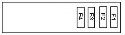
|
№ |
Purpose |
|
F1 -
F2
|
Air pump for the exhaust air mixing system
|
|
F3
|
Diesel Engine Fuel Filter Preheater Fuse
|
|
F4
|
Diesel Engine Glow Plug Fuse
|
Mounting block of relays and fuses in the left part of the engine compartment of models from 1995 with K/V
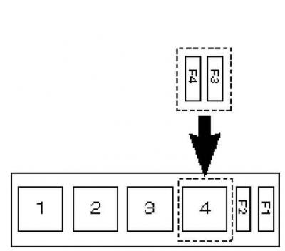
|
№ |
Purpose |
|
F1 -
F2
|
Air pump for the exhaust air mixing system
|
|
F3
|
Diesel Engine Fuel Filter Preheater Fuse
|
|
F4
|
Diesel Engine Glow Plug Fuse
|
|
1
|
A/C compressor relay
|
|
2
|
Relay I condenser fan K/V
|
|
3
|
Relay II condenser fan K/V
|
|
4
|
Relay III condenser fan K/V
|
Fuses in the main fuse box
Main fuse box fuse layout diagram
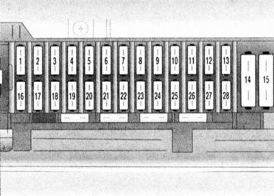
|
№ |
Electrical circuit
|
Current strength, A
|
| 1
|
Hazard warning lights, anti-theft alarm siren, interior and trunk lighting
|
20
|
| 2
|
Automatic transmission
|
10
|
| 3
|
Rear window heating, anti-theft device
|
30
|
| 4
|
Daytime running lights
|
10
|
| 5
|
Automatic transmission
|
10
|
| 6
|
Reversing lights and rear fog lights
|
10
|
| 7
|
Air conditioner
|
30
|
| 8
|
Left parking light, left rear position light
|
20
|
| 9
|
Sliding roof panel
|
20
|
| 10
|
Left high beam headlight
|
10
|
| 11
|
Headlight lens washer
|
30
|
| 12
|
Left low beam headlight, headlight range adjustment
|
10
|
| 13
|
Single lock
|
20
|
| 14
|
Rear window heating
|
|
| 15
|
Heater and A/C fan
|
30
|
| 16
|
Wiper
|
30
|
| 17
|
Radio, information display, alarms, A/V, glove compartment lighting, power windows, power outside mirrors, power steering
|
10
|
| 18
|
Single lock, reversing lights, speedometer, automatic transmission, heated seats and rear window, cigarette lighter
|
20
|
| 19
|
K/L headlights, daytime running lights
|
10
|
| 20
|
Fan K/V
|
30
|
| 21
|
Brake lights and hazard warning lights
|
15
|
| 22
|
ABS
|
10
|
| 23
|
Right parking light, right rear position light, number plate light
|
10
|
| 24
|
Air conditioner
|
15
|
| 25
|
Right high beam headlight
|
10
|
| 26
|
Fuel pump, fuel injection system
|
20
|
| 27
|
Right low beam headlight, headlight range adjustment
|
10
|
| 28
|
Window lifters
|
30
|
Relay in the main mounting block
Relay layout diagram in the main mounting block
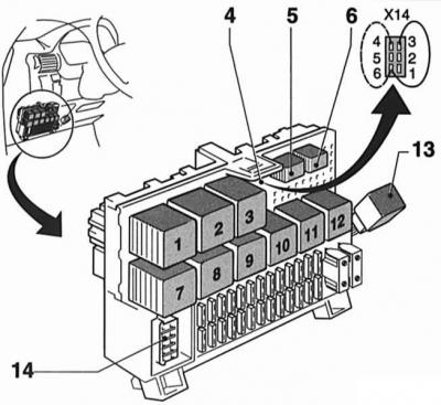
|
№ |
Purpose |
| 1 | Heated outside mirror (time relay) |
| 2 | Turn signal relay |
| 3 | Intermittent rear window wiper operation |
| 4 | Fog Light Encoding (6-pin) |
| 5 | Fog lights |
| 6 | Fog lights |
| 7 | Interval windshield wiper operation mode |
| 8 | Rear window heating |
| 9 | Warning buzzer for headlights on |
| 10 | Anti-theft alarm system siren |
| 11 | Headlight lens washer pump (delay relay) |
| 12 | Anti-theft alarm starter relay |
| 13 | DRL |
| 14 | DLC, depending on the version, 10-, 14- or 16-pin |
Relay in the mounting block above the glove compartment
Location of the relay in the mounting block above the glove compartment of models up to 1994 issue No. Purpose
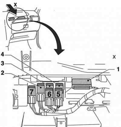
|
№ |
Purpose |
| 1 | Anti-theft alarm (control unit) |
| 2 | Condenser radiator fan K/V (relay K51) |
| 3 | Condenser radiator fan K/V (relay K52) |
| 4 | Condenser radiator fan K/V (relay K26) |
| 5 | K/V |
| 6 | Fan K/V |
| 7 | Condenser radiator fan K/V, 2nd speed |
On models with a front passenger airbag, the A/C relay is located on the right side, next to the glove compartment.
The location of the relay in the mounting block above the glove compartment of models from 1994 onwards.
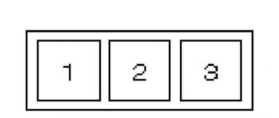
|
№ |
Purpose |
| 1 | Relay I condenser radiator fan K/V (up to 1995.) |
| 2 | Relay II condenser radiator fan K/V (up to 1995.) |
| 2 | K/V relay (since 1996.) |
| 3 | Relay III condenser radiator fan K/V (up to 1995.) |
Relay in the mounting block behind the right A-pillar trim
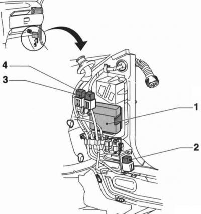
|
№ |
Purpose |
| 1 | MulTec system control unit |
| 2 | Fuel pump relay |
| 3 | Diesel Glow Plug Relay |
| 4 | Battery charge control relay |
Lighting fixtures lamps
|
Purpose |
Power, W |
| High/low beam (type H14) |
60/55
|
| Fog lights (type H3) |
55
|
| Side direction indicator, number plate, trunk and interior lighting |
10
|
| Front and rear turn signals, rear fog lights, reversing lights |
21
|
| Brake light/tail light |
21/5
|
| Front parking light |
5
|
SRS fault codes
|
Code |
Source of malfunction |
| 2 | Driver side airbag circuit fault |
| 3 | Malfunction in the front passenger side airbag circuit |
| 4 | Malfunction in the front driver airbag module circuit |
| 5 | Front passenger airbag module malfunction |
| 6 | Malfunction in the passenger seat belt pretensioner module circuit |
| 7 | Passenger Seat Belt Pretensioner Module Malfunction |
| 8 | The signal level is too low (short to ground) in the driver's side airbag module circuit |
| 9 | The signal level is too low (short to ground) in the passenger side airbag module circuit |
| 12,13 | For a short circuit to the housing in the driver's airbag circuit |
| 14 | Short to ground in left seat belt tensioner circuit |
| 15 | Short to ground in driver airbag circuit |
| 16 | Short circuit in the left seat belt tensioner circuit |
| 21 | Models before 1995: Short circuit to ground in one of the airbag circuits
Models before 1995: Short to ground in driver airbag circuit |
| 22 | Models before 1995: Short circuit in one of the airbags
Models before 1995: Short circuit in driver airbag circuit |
| 23 | Short to ground in front passenger airbag circuit |
| 24 | Short to ground in right seat belt tensioner circuit |
| 25 | Short circuit in front passenger airbag circuit |
| 26 | Short circuit in the right seat belt tensioner circuit |
| 31 | Excessively high electrical resistance in the front driver airbag module circuit |
| 32 | Electrical resistance in the front driver airbag module circuit is excessively low |
| 33 | Electrical resistance in the front passenger airbag module circuit is excessively high |
| 34 | Electrical resistance in the front passenger airbag module circuit is excessively low
On models prior to 1998: The SRS control unit has detected the front passenger airbag |
| 35 | Excessively high electrical resistance in the driver's seat emergency tensioner module circuit |
| 36 | The electrical resistance in the driver's seat emergency tensioner module circuit is excessively low |
| 37 | Electrical resistance in the passenger seat emergency tensioner module circuit is excessively high |
| 38 | Electrical resistance in the passenger seat emergency tensioner module circuit is excessively low |
| 43 | SRS warning light signal is too high |
| 44 | SRS warning light signal is too low |
| 45 | Short circuit in front passenger airbag deactivation circuit K/L |
| 46 | Short to ground or open in front passenger airbag deactivation circuit K/L |
| 48 | Low supply voltage |
| 49 | High supply voltage |
| 51,52 | SRS control module not programmed |
| 53 | SRS control module software error |
| 55 | SRS control module malfunction |
| 56 | SRS control module malfunction |
| 65 | The front passenger airbag has deployed |
| 66 | The front driver's airbag deployed |
| 67 | The emergency seat belt tensioner has been activated |
| 68 | The passenger side airbag deployed |
| 69 | The driver's side airbag deployed |
| 71 | Driver's side airbag directional overload sensor signal level is too high |
| 72 | Malfunction in the driver's side airbag directional overload sensor circuit |
| 75 | Short to ground in driver side airbag directional overload sensor circuit |
| 76 | Short circuit in the driver's side airbag directional overload sensor circuit |
| 77 | Driver's side airbag electrical resistance too high |
| 78 | The electrical resistance of the driver's side airbag is excessively low |
| 79 | Driver's side airbag directional overload sensor malfunction |
| 81 | Passenger side airbag directional overload sensor signal level is too high |
| 82 | Malfunction in the directional overload sensor circuit of the passenger side airbag |
| 85 | Short to ground in front passenger side airbag directional overload sensor circuit |
| 86 | Short circuit in the front passenger side airbag directional overload sensor circuit |
| 87 | Electrical resistance of passenger side airbag is excessively high |
| 88 | Electrical resistance of passenger side airbag is too low |
| 89 | Malfunction of the directional overload sensor of the passenger side airbag |
| 90 | Communication error with front passenger presence sensor |
| 92 | Malfunction in the front passenger presence sensor circuit |
| 93 | The front passenger presence sensor is faulty |
| 95 | The special child seat detection sensor is faulty |
| 98 | Short to ground in airbag alarm circuit |
| 99 | Short circuit to ground in the circuit |
| 101 | Driver's side airbag electrical resistance too high |
| 102 | The electrical resistance of the driver's side airbag is excessively low |
| 103 | Electrical resistance of passenger side airbag is excessively high |
| 104 | The electrical resistance of the passenger side airbag is too low |
Original source is on the website [www.opelbook.ru]
Visitor comments