


Front suspension design
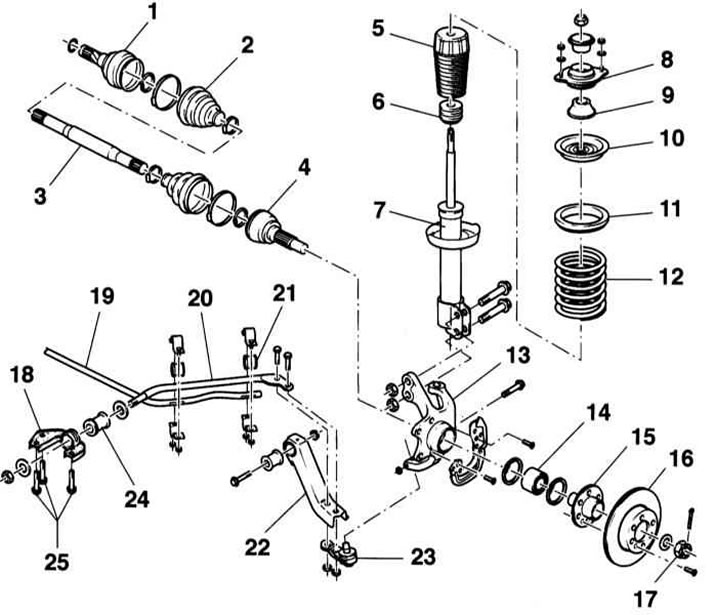
1 — Inner CV joint
On dOHC engines 1.0 and 1.2 l:
Tripod joint.
2 — Inner CV joint cover
3 — Drive shaft
4 — Outer CV joint
5 - Cover
6 — Compression stroke buffer
7 — Shock absorber
8 — Thrust bearing
9 — Spacer
10 — Upper spring cup
11 — Damping ring
12 — Spring
13 — Steering knuckle
14 — Wheel bearing
15 — Wheel hub
16 — Brake disc
17 — Crown hub nut
18 — Rod holder
19 - Stabilizer bar
20 — Thrust
21 - Rubber support
22 — Suspension wishbone
23 — Ball joint
24 — Damping bushing
25 - Flange bolts
The Opel Corsa and Tigra are equipped with a rear suspension with levers and a connecting beam. The suspension consists of an open cross tube, to which a longitudinal lever is welded on each side. An additional stabilizer is located in the cross tube. The longitudinal levers are connected to the body through rubber-metal supports with bolts. Coil springs and hydraulic shock absorbers are used to reduce the feeling of unevenness in the road. The rear wheel bearings are adjustable. The Combo model has a rigid axle with leaf springs and shock absorbers, which are characterized by high strength. This design allows for a significantly greater vehicle load. Compared to the models Corsa B and Tigra the design of the rear wheel bearings has also been changed. They are not built into the brake drums, but are located in a separate hub, which is attached to the brake drum with bolts.
Rear suspension design of Corsa and Tigra models
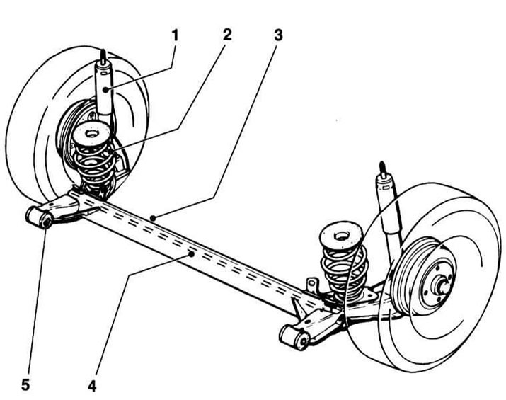
1 — Shock absorber
2 - Coil spring
3 - Connecting beam
4 — Anti-roll bar
5 — Damping bushing
Rear suspension design of Combo models
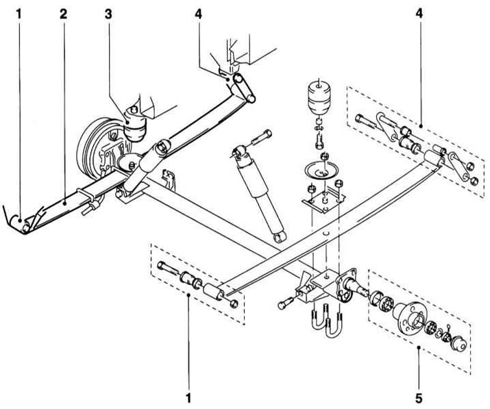
1 - Front spring mount
2 — Spring
3 - Additional spring
4 — Rear spring mount
5 - Wheel hub assembly
Since 09.1997, the design of the wheel bearing hub cap has been changed on Combo models.
The steering gear consists of a steering wheel, steering shaft and steering rods. The steering wheel is fixed to the steering shaft, which is connected to the steering gear. The rotation of the steering shaft is transmitted to the toothed rack via a rack-and-pinion engagement. The toothed rack is connected to the steering rods via ball joints. The latter transmit movement to the front wheels of the car via joints and steering knuckles. The steering gear should have an easy movement and should not have any play. It does not require maintenance, but during maintenance it is necessary to check the tightness of the sealing cuffs. Depending on the model and configuration of the car, it can be equipped with a power steering (GUR). Cars with engines DOHC 1.0 and 1.2 l equipped with electric power steering (EPS); on cars with OHC engines from 1.2 to 1.7 l a conventional power steering is used. The task of the power steering is to reduce the effort required to turn the steering wheel, primarily at low speeds or when parked.
Steering column design
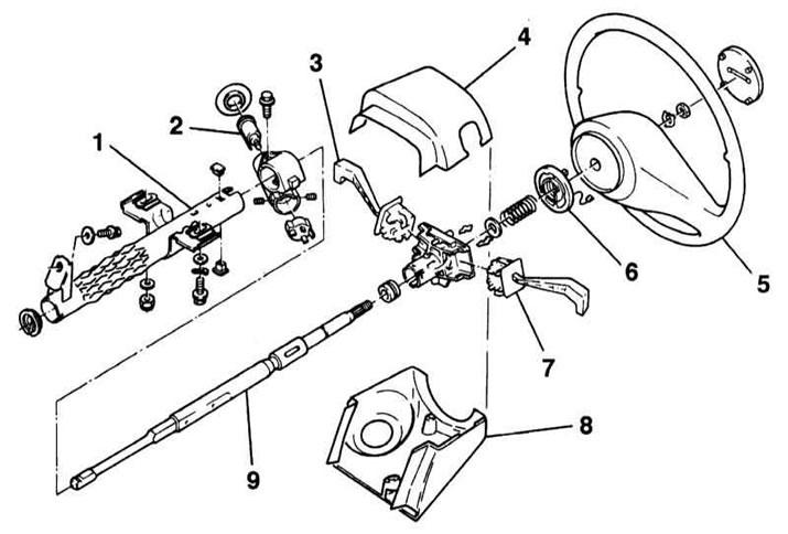
1 - Steering column cover
2 — Ignition lock cylinder
3 — Windscreen wiper stalk
4 - Upper steering column cover
5 - Steering wheel
6 - Cable drum
7 — Steering column switch for exterior lighting
8 — Lower steering column trim
9 — Steering shaft
Design of a steering drive without power steering
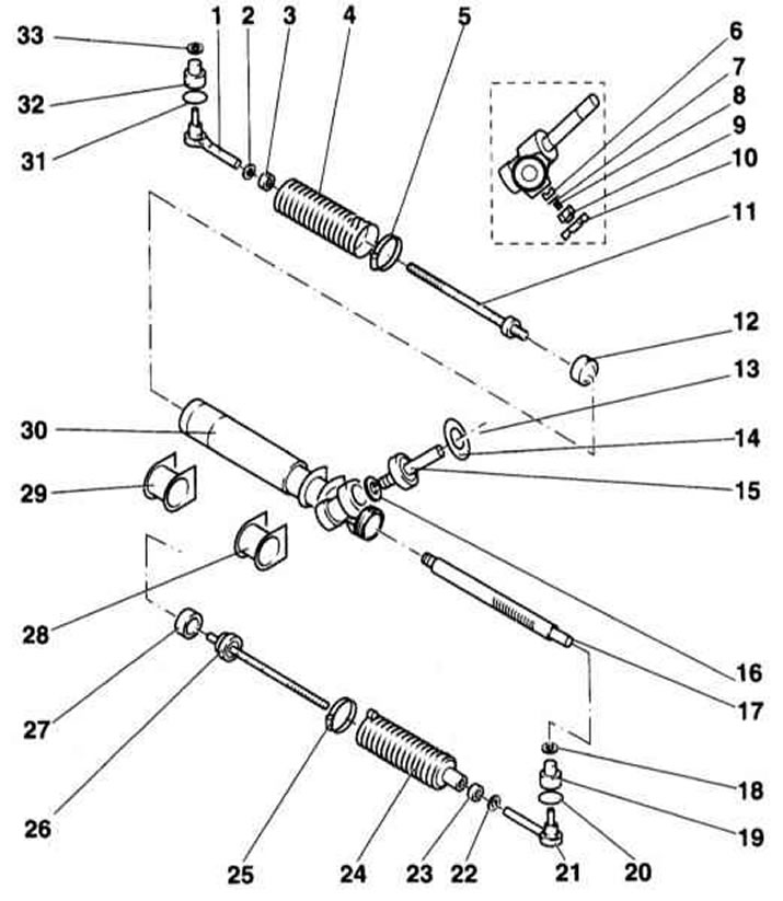
1 — Tie rod end
2 — Lock nut
3 — Protective casing clamp
4 - Protective cover
5 — Protective casing clamp
6 — Support and pressure element
7 — Sealing ring
8 — Spring
9 — Adjusting plug
10 — Lock nut
11 — Steering rod
12 — Thrust ring
13 — Sealing ring
14 — Retaining ring
15 - Gear with bearing
16 — Guide bushing
17 — Toothed rack
8 — Lock nut
19 — Dust cover
20 — Retaining ring
21 — Tie rod end
22 — Lock nut
23 — Protective casing clamp
24 - Protective cover
25 — Protective casing clamp
26 — Steering rod
27 — Thrust ring
28 - Left rubber support
29 - Right rubber support
30 — Steering gear housing
31 — Retaining ring
32 — Dust cover
33 — Lock nut
The power steering consists of a pump, a power steering fluid reservoir and connecting hoses. The pump is driven by the engine via a V-belt. The pump supplies fluid from the reservoir under high pressure to the valve body located in the steering gear. The valve is connected to the steering shaft and supplies oil depending on the direction of rotation of the steering wheel to the corresponding side of the power steering working cylinder. The fluid acts on the piston and thus facilitates the process of turning the wheels. At the same time, the piston squeezes out fluid from the other side of the working cylinder through the return hydraulic line into the reservoir.
The operating principle of EPS is as follows. The rotation of the steering wheel is registered by the torque sensor (3), the signal is transmitted to the EPS control unit (5). From the VSS and ECM, the EPS control unit receives information about the speed of the vehicle. The EPS control unit calculates the required amount of force, which is created by the electric motor (1) and transmits it to the steering gear (8). The magnitude and direction of the auxiliary force are determined by the magnitude of the electric motor current, determined by the EPS control unit. A direct mechanical connection between the steering wheel and the steering gear is carried out via the lower steering shaft (7). Thus, if the EPS fails, the vehicle remains controllable. EPS only works when the engine is running.
Electric Power Steering Design (dOHC models 1.0 and 1.2 l)
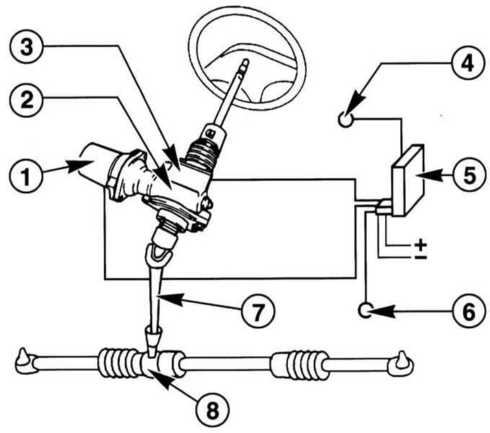
1 - Electric motor
2 - Worm gear
3 - Torque sensor
4 - Signal from VSS
5 — EPS control unit
6 — Crankshaft speed signal from ECM
7 — Lower steering shaft
8 — Steering mechanism
Often, when servicing suspension components, you have to deal with fasteners that cannot be loosened. The fasteners "stick" because they are constantly exposed to external influences, are in contact with water, dirt, soot and other substances that promote corrosion. In order to facilitate the procedure of loosening such "stuck" fasteners, they should be soaked in a large amount of penetrating oil beforehand. Cleaning the exposed threaded parts of the fasteners with a hard wire brush also helps to loosen rusted nuts. Sometimes, in especially difficult cases, you can use a drift to loosen a "stuck" bolt/nut. The drift rests against the edge of the nut/bolt head slot, then sharp blows are applied to its opposite end with a hammer. Make sure that the drift does not come off, try not to damage the thread with inaccurate blows. Another quite effective method is to heat the fastener that is difficult to loosen and the surface of the component around it with a blowtorch or gas torch, although the authors of this Guide do not recommend resorting to this technology unless absolutely necessary due to its potential danger associated with the possibility of fire and the risk of burns. Various types of extensions, collars and pipe attachments are designed to increase the torque when loosening the fastener. However, remember that you should not use such reinforcing devices in a set with a ratchet-equipped drive - the risk of failure of the ratchet mechanism is too great. Sometimes a nut/bolt begins to give in after it has been slightly tightened clockwise. All fasteners, the loosening of which required the use of extraordinary measures during assembly, are subject to replacement!
After delivery, carefully check the condition of the fasteners and, if necessary, replace them with elements of the same size. When assembling, tighten the fasteners of the suspension and steering components strictly with the required force.
Do not attempt to straighten deformed suspension and steering components under any circumstances - replace defective parts with new ones!
Since suspension component maintenance procedures are performed under the vehicle, care must be taken in advance to ensure that the vehicle can be lifted and secured in the raised position (prepare a reliable jack and supports).
Never perform any work under a vehicle that is secured in a raised position using only a jack!
Precautionary measures
The steering wheel has an airbag built into the hub. To ensure that the airbag deploys properly in an accident and to avoid the risk of injury from accidental deployment, certain precautions must be taken (see also Chapter On-board electrical equipment):
- Before starting work on the airbag or near the SRS wiring route, be sure to disconnect the negative battery cable. Work should be started at least one minute after disconnecting the battery - time is needed to discharge the backup power supply capacitor;
- Do not allow the airbag module to heat up to over 90°C. Do not turn the removed airbag module upside down;
- Avoid contact of the module surface with solvents and detergents - use only a clean, slightly damp cloth to wipe the steering wheel;
- The SRS control unit and airbag modules are sensitive to directional overloads (impacts) and must be replaced after a fall from a height of more than 50 cm;
- Before carrying out welding work on the vehicle, be sure to disconnect the SRS control unit wiring;
- On models equipped with passenger air bags, to avoid injury, do not install any additional equipment or place any foreign objects in the air bag deployment area.
Visitor comments