
OpelBook.ru
Cars AvtoVAZ Cars Mitsubishi Cars BMW Cars Mercedes Cars Nissan Cars Toyota Cars Chevrolet
English Русский
Български
Беларускі
Український
Српски
Hrvatski
Română
Polski
Slovenský
Magyar
 |  Sitemap  |  Contacts  |    


Main Astra Corsa Insignia Kadett Omega Vectra Zafira Others Articles
Astra F (1991-1998, petrol) Astra G (1998-2004, petrol) Astra G (1998-2004) Astra H (2004-2009) Astra J (2009-2015, petrol)
  • Main
  • Astra
  • Astra J
  • Power unit
  • Exhaust system
  • Design features of the exhaust system

Design features of the exhaust system (Opel Astra J)

            0

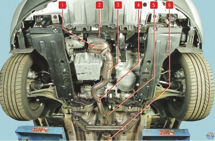
Exhaust gases are discharged from the engine through the exhaust manifold 1 (Fig. 1) (exhaust manifold combined with a catalytic converter), intake pipe 4, additional 6 and main 4 (Fig. 2) mufflers.

Fig. 1. Location of exhaust system components in the front part of the body base: 1 – cat…

Fig. 1. Location of exhaust system components in the front part of the body base: 1 – cat collector; 2 – heat shield of the catalytic collector; 3 – bellows; 4 – intake pipe; 5 – additional muffler heat shield; 6 – additional muffler
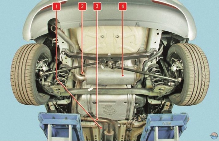

Fig. 2. Location of exhaust system components in the rear part of the body base: 1 – heat shield of…

Fig. 2. Location of exhaust system components in the rear part of the body base: 1 – heat shield of the exhaust pipe of the additional muffler; 2 – heat shield of the main muffler; 3 – exhaust pipe of additional muffler; 4 – main muffler


On catcollector 1 (see fig. 1) the main one is installed (control) oxygen concentration sensor, and on the inlet pipe 4 there is a diagnostic oxygen concentration sensor.


On catcollector 1 (see fig. 1) the main one is installed (control) oxygen concentration sensor, and…


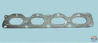
A metal-reinforced sealing gasket is installed between the cylinder head and the exhaust manifold flange.

The inlet pipe is connected at one end to the flange of the exhaust manifold, and at the other end to the inlet pipe of the additional muffler 6. In turn, the outlet pipe of the additional muffler is connected to the inlet pipe of the main muffler 4 (see fig. 2).
The inlet pipe is connected at one end to the flange of the exhaust manifold, and at the other end…


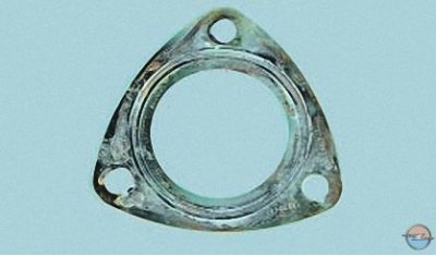
The flange connection of the exhaust manifold and the inlet pipe is sealed with a metal-reinforced gasket.
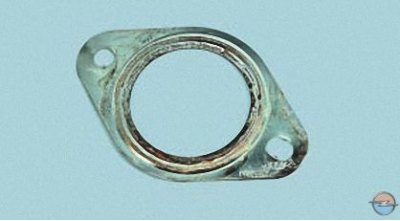
The flange connection of the exhaust manifold and the inlet pipe is sealed with a metal-reinforced…


With a similar gasket (just a different shape) the flange connection of the inlet pipe and the additional muffler is sealed.


The remaining connections of the system are welded; when replacing individual elements, the connecting pipes are cut and then the new elements are secured with clamps, each of which is welded at one point to the pipes of the main and additional mufflers.

In order to reduce the transmission of vibrations from the power unit to the exhaust system and body, a corrugated vibration-compensating bellows 3 is mounted in the intake pipe (see fig. 1) in a metal braid.
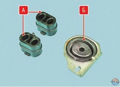
In order to reduce the transmission of vibrations from the power unit to the exhaust system and…


The system elements are suspended from the body on five rubber cushions A and the rear support B main muffler.

To protect the cooling system radiator, body base and fuel tank from heating by system elements, steel heat shields are installed on the exhaust manifold, the exhaust pipe of the additional muffler and the main muffler, respectively 2 (see fig. 1), 1 and 2 (see fig. 2).

The exhaust system does not require special maintenance. It is enough to periodically check the reliability of tightening of threaded connections and the integrity of the suspension cushions. In case of damage to system elements, through corrosion or burnout, they are replaced as a whole, since the mufflers together with the pipes are not disassemblable units.


However, there are separate parts of the exhaust system available for sale (for example, the main muffler). They can be replaced by cutting off the damaged part and installing a new one using special connecting clamps. The muffler pipes should be cut on their straight sections (depending on the design of new parts)...
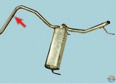
However, there are separate parts of the exhaust system available for sale (for example, the main…


…for example, in the place shown by the arrow.

Useful tips


Check the exhaust system periodically. If the exhaust system is noisy, check for leaks. To do this, start the engine and inspect the entire system. Run your hand over the possible leaks without touching the components, and you will immediately feel the gas leak. If necessary, replace rusted and burnt components.

If it is impossible to replace the defective unit with a new one, you can temporarily restore its functionality by applying a metal patch to the damaged area and securing it with clamps or wire. It is recommended to put a sheet of asbestos under the patch.

In addition, auto parts stores sell special kits for restoring exhaust system components, which can be used to temporarily repair damage to the system in order to get to a car service center or garage.


Caution! Allow the exhaust system to cool before repairing, as it reaches high temperatures during engine operation.


Exhaust gases are toxic, and poisoning occurs unnoticed, so be sure to open the garage door before starting the engine!

To remove and install system components you will need: keys "13", "16", "22", socket heads "10", TORX E12, flat-blade screwdriver.


This article is available at russian, bulgarian, belarusian, ukrainian, serbian, croatian, romanian, polish, slovak, hungarian
Checking the article: Trifonova Emilia

Share information:

Previous articles
Opel Astra J: Exhaust system
Next articles

Removal, checking and installation the purge valve of the adsorber
Removal and installation the fuel vapor recovery system canister
Features of the fuel vapor recovery system
Replacing the exhaust system suspension cushions
Replacing the main and additional mufflers
Replacing the inlet pipe
Removal and installation the catalytic converter, replacing its gasket
Removal and installation of thermal screens


See similar ones from other Opel car manuals:
▶ Exhaust system — design description Opel Zafira A (1999-2005, petrol)
▶ Checking the exhaust system Opel Corsa B (1993-2000)
▶ Features of the lighting system Opel Insignia A (2008-2017)
▶ Device of the exhaust gas system Opel Kadett E (1984-1995)
▶ Exhaust system — removal and installation Opel Omega A (1986-1993)
Link to this page in different formats

Visitor comments


No comments yet


How much will 18 + 45 =


Astra J (2009-2015, petrol) 
  • General information
  • Vehicle device
  • User manual
  • Faults en route
  • Maintenance
  • Power unit
  • Engine repair
  • Cooling and lubrication system
  • Engine power system
  • Exhaust system
  • Transmission
  • Clutch
  • Car gearbox
  • Drive shafts
  • Chassis
  • Front suspension
  • Rear suspension
  • Steering
  • Brake system
  • Wheels and tires
  • Body
  • Exterior
  • Interior
  • Doors and windows
  • Body Care
  • Heating and air conditioning
  • Security systems
  • Electrical equipment
  • Equipment and devices
  • Lighting and signaling
  • Power devices
  • Electrical circuits
Astra H (2004-2009) 
  • General information
  • Introduction to the guide
  • Troubleshooting
  • User manual
  • Maintenance
  • Power unit
  • Engine repair
  • Cooling and heating
  • Power and exhaust system
  • Ignition system
  • Launch and charge system
  • Transmission
  • Mechanical gearbox
  • Automatic gearbox
  • Drive shafts
  • Chassis
  • Brake system
  • Car suspension
  • Steering
  • Body
  • Interior
  • Exterior
  • Electrical equipment
  • Equipment and devices
  • Electrical circuits
Astra G (1998-2004) 
  • General information
  • Introduction to manual
  • User manual
  • Maintenance
  • Power unit
  • SOHC gasoline engines
  • DOHC gasoline engines
  • Diesel engines 1.7 and 2.0
  • Engine repair
  • Cooling system
  • Supply system
  • Injection system (gasoline)
  • Injection system (diesel)
  • Exhaust system
  • Charge and launch system
  • Ignition system (gasoline)
  • Preheat system (diesel)
  • Transmission
  • Manual gearbox
  • Automatic gearbox
  • Clutch
  • Drive shafts
  • Chassis
  • Brake system
  • Wheel suspension
  • Steering
  • Body
  • Exterior
  • Interior
  • Doors and windows
  • Ventilation and heating
  • Electrical equipment
  • Equipment and devices
  • Electrical circuits
Astra G (1998-2004, petrol) 
  • General information
  • User manual
  • Car care
  • Maintenance
  • Power unit
  • Single shaft engines
  • Twin shaft engines
  • Engine repair
  • Cooling and heating
  • Fuel and exhaust systems
  • Starting and charging system
  • Ignition system
  • Transmission
  • Clutch
  • Mechanical gearbox
  • Automatic gearbox
  • Drive shafts
  • Chassis
  • Brake system
  • Car suspension
  • Steering
  • Body
  • Interior
  • Exterior
  • Electrical equipment
  • Equipment and devices
  • Wiring diagrams Opel Astra
  • Wiring diagrams Opel Zafira
Astra F (1991-1998, petrol) 
  • General information
  • Maintenance
  • Power unit
  • Engine in car
  • Engine removed
  • Cooling system
  • Heating and ventilation
  • Fuel supply (carburetor)
  • Fuel supply (injector)
  • Emission control
  • Ignition system
  • Transmission
  • Clutch
  • Mechanical gearbox
  • Automatic gearbox
  • Drive shafts
  • Chassis
  • Brake system
  • Car suspension
  • Steering
  • Body
  • Exterior
  • Interior
  • Electrical equipment
  • Equipment and devices
  • Electrical circuits
OpelBook.ru © 2017–2026 · Mobile version · · Sitemap: EN BG BY UA RS HR RO PL SK HU · Feedback · Site search
Astra F, petrol · Astra G, petrol · Astra G · Astra H · Astra J, petrol · Corsa B · Corsa C, petrol · Corsa C · Insignia A · Kadett D · Kadett E · Omega A · Omega B · Omega B2 · Vectra A, petrol · Vectra A · Vectra B, petrol · Vectra B · Vectra C · Zafira A, petrol · Frontera A, petrol · Frontera B · Ascona C · Vivaro A ·
We want your visit to be comfortable 🤝! We use cookies 🍪 to make that happen.