OpelBook.ru
Cars AvtoVAZ Cars Mitsubishi Cars BMW Cars Mercedes Cars Nissan Cars Toyota Cars Chevrolet
English Русский
Български
Беларускі
Український
Српски
Hrvatski
Română
Polski
Slovenský
Magyar
 |  Sitemap  |  Contacts  |    


Main Astra Corsa Insignia Kadett Omega Vectra Zafira Others Articles
Astra F (1991-1998, petrol) Astra G (1998-2004, petrol) Astra G (1998-2004) Astra H (2004-2009) Astra J (2009-2015, petrol)
  • Main
  • Astra
  • Astra G
  • Power unit
  • Single shaft engines
  • Cylinder head — removal and installation

Cylinder head — removal and installation (Opel Astra G)

            0

Contents: Preparing for assembly ⬇ Installation ⬇
1. Decompress the fuel system (Chapter 4A) and disconnect the battery from ground.

2. Drain the coolant.

3. Remove the camshaft belt.

4. Remove the engine support bracket on the right side of the cylinder head by unscrewing the bolts.

5. Remove both manifolds. The cylinder head can be removed without removing the manifolds by following these steps:.

A. Disconnect the wires and hoses from the throttle body and intake manifold.

B. Loosen the bolts and remove the intake manifold support and upper generator bracket.

B. Disconnect the exhaust pipe from the manifold, disconnect the connector from the oxygen sensor.

6. Remove the cylinder head cover, camshaft sprocket and unscrew the bolts securing the rear cover to the camshaft bearing housing.

7. Mark and disconnect the wires from the cylinder head, disconnect the hose from the thermostat housing.

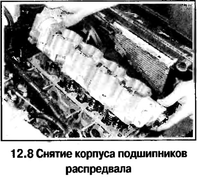
8. In the reverse order of the indicated (see photo below) gradually loosen the bolts (doing ⅓ of a turn per reception) and remove the camshaft bearing housing (see photo). If necessary, displace the housing with light blows of a soft-faced hammer; do not pry the bearing housing by the split plane. Remove the guide pins if they become loose.
8. In the reverse order of the indicated (see photo below) gradually loosen the bolts (doing ⅓ of a…


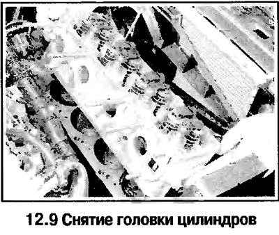
9. Remove the cylinder head. Dislodge the stuck head with light blows of a soft-faced hammer. Remove the guide pins and gasket.


9. Remove the cylinder head. Dislodge the stuck head with light blows of a soft-faced hammer.…


Preparing for assembly


10. Clean the separating surfaces of the head and block, closing all openings to prevent dirt from getting in. Cover the gaps in the pistons with grease, which is then removed.

11. Check for damage on the separating surfaces of the cylinder head and block (deep scratches, chips, etc.). Minor defects are removed with a file, serious damage is removed by grinding the block and head.

12. Check the deformation of the separating surfaces of the head and block.

13. Clean the threads in the cylinder head and tap them with a tap.

14. Replace the cylinder head bolts.

Installation


15. Set the piston of the 1st cylinder to TDC of the compression stroke.

16. Wipe dry the separating surfaces of the head and cylinder block. Make sure the guide pins are present.

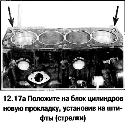
17. Place a new gasket on the cylinder block (the OBEN/TOP inscription should be facing up – photo).
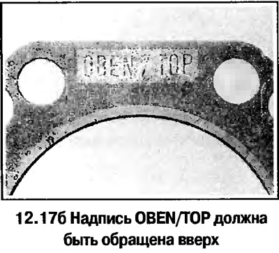
17. Place a new gasket on the cylinder block (the OBEN/TOP inscription should be facing up – photo).


17. Place a new gasket on the cylinder block (the OBEN/TOP inscription should be facing up – photo).


18. Check the alignment of the marks on the crankshaft sprocket and the oil pump housing by placing the sprocket in place. Apply to the upper split plane of the head (under the bearing housing) sealant (see photo). Install the cylinder head onto the pins.


18. Install the camshaft bearing housing onto the pins.
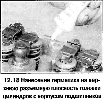
18. Install the camshaft bearing housing onto the pins.


19. Carefully insert the bolts into the corresponding holes in the cylinder head (do not drop the bolts), tighten them by hand (see photo).
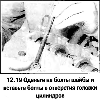
19. Carefully insert the bolts into the corresponding holes in the cylinder head (do not drop the…


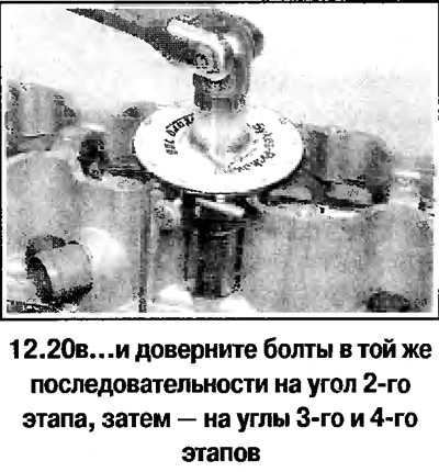
20. Tighten the cylinder head bolts in the sequence shown (see photo) with the torque of the 1st stage of tightening. Tighten the bolts in the same sequence first to the angle of the 2nd stage, then to the angles of the 3rd and 4th stages.
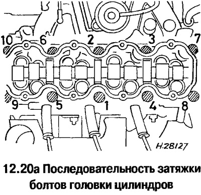
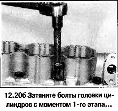
20. Tighten the cylinder head bolts in the sequence shown (see photo) with the torque of the 1st…


20. Tighten the cylinder head bolts in the sequence shown (see photo) with the torque of the 1st…


20. Tighten the cylinder head bolts in the sequence shown (see photo) with the torque of the 1st…


21. Tighten the bolts securing the rear cover to the camshaft bearing housing.


22. Install the engine support bracket to the right side of the cylinder head. Tighten the bolts.

23. Then assembly is carried out in reverse order.

Original posted on the website: www.opelbook.ru


This article is available at russian, bulgarian, belarusian, ukrainian, serbian, croatian, romanian, polish, slovak, hungarian
Checking the article: Kornev Georgy

Share information:

Previous articles
Opel Astra G: Single shaft engines
Next articles

Hydraulic tappets — removal and installation
Camshaft Bearing Housing and Camshaft — Removal and Installation
Camshaft Seal — Replacement
Tensioner and sprockets — removal and installation
Timing Belt for Camshaft Drive — Removal and Installation
Timing Belt Covers — Removal and Installation
Oil pan — removal and installation
Oil pump — removal, inspection and installation
Flywheel/torque converter drive disc — removal and installation
Crankshaft seals — replacement
Powertrain Mounts — Removal and Installation


See similar ones from other Opel car manuals:
▶ Removal and installation the cylinder head Opel Corsa B (1993-2000)
▶ Cylinder head cover Opel Insignia A (2008-2017)
▶ Cylinder head specifications Opel Kadett E (1984-1995)
▶ Cylinder head — removal and installation with engine in car Opel Omega A (1986-1993)
▶ Cylinder head — removal and installation (engine in a car) Opel Vectra A (1988-1995, petrol)
Link to this page in different formats

Visitor comments


No comments yet


How much will 16 + 20 =


Astra J (2009-2015, petrol) 
  • General information
  • Vehicle device
  • User manual
  • Faults en route
  • Maintenance
  • Power unit
  • Engine repair
  • Cooling and lubrication system
  • Engine power system
  • Exhaust system
  • Transmission
  • Clutch
  • Car gearbox
  • Drive shafts
  • Chassis
  • Front suspension
  • Rear suspension
  • Steering
  • Brake system
  • Wheels and tires
  • Body
  • Exterior
  • Interior
  • Doors and windows
  • Body Care
  • Heating and air conditioning
  • Security systems
  • Electrical equipment
  • Equipment and devices
  • Lighting and signaling
  • Power devices
  • Electrical circuits
Astra H (2004-2009) 
  • General information
  • Introduction to the guide
  • Troubleshooting
  • User manual
  • Maintenance
  • Power unit
  • Engine repair
  • Cooling and heating
  • Power and exhaust system
  • Ignition system
  • Launch and charge system
  • Transmission
  • Mechanical gearbox
  • Automatic gearbox
  • Drive shafts
  • Chassis
  • Brake system
  • Car suspension
  • Steering
  • Body
  • Interior
  • Exterior
  • Electrical equipment
  • Equipment and devices
  • Electrical circuits
Astra G (1998-2004) 
  • General information
  • Introduction to manual
  • User manual
  • Maintenance
  • Power unit
  • SOHC gasoline engines
  • DOHC gasoline engines
  • Diesel engines 1.7 and 2.0
  • Engine repair
  • Cooling system
  • Supply system
  • Injection system (gasoline)
  • Injection system (diesel)
  • Exhaust system
  • Charge and launch system
  • Ignition system (gasoline)
  • Preheat system (diesel)
  • Transmission
  • Manual gearbox
  • Automatic gearbox
  • Clutch
  • Drive shafts
  • Chassis
  • Brake system
  • Wheel suspension
  • Steering
  • Body
  • Exterior
  • Interior
  • Doors and windows
  • Ventilation and heating
  • Electrical equipment
  • Equipment and devices
  • Electrical circuits
Astra G (1998-2004, petrol) 
  • General information
  • User manual
  • Car care
  • Maintenance
  • Power unit
  • Single shaft engines
  • Twin shaft engines
  • Engine repair
  • Cooling and heating
  • Fuel and exhaust systems
  • Starting and charging system
  • Ignition system
  • Transmission
  • Clutch
  • Mechanical gearbox
  • Automatic gearbox
  • Drive shafts
  • Chassis
  • Brake system
  • Car suspension
  • Steering
  • Body
  • Interior
  • Exterior
  • Electrical equipment
  • Equipment and devices
  • Wiring diagrams Opel Astra
  • Wiring diagrams Opel Zafira
Astra F (1991-1998, petrol) 
  • General information
  • Maintenance
  • Power unit
  • Engine in car
  • Engine removed
  • Cooling system
  • Heating and ventilation
  • Fuel supply (carburetor)
  • Fuel supply (injector)
  • Emission control
  • Ignition system
  • Transmission
  • Clutch
  • Mechanical gearbox
  • Automatic gearbox
  • Drive shafts
  • Chassis
  • Brake system
  • Car suspension
  • Steering
  • Body
  • Exterior
  • Interior
  • Electrical equipment
  • Equipment and devices
  • Electrical circuits
OpelBook.ru © 2017–2026 · Mobile version · · Sitemap: EN BG BY UA RS HR RO PL SK HU · Feedback · Site search
Astra F, petrol · Astra G, petrol · Astra G · Astra H · Astra J, petrol · Corsa B · Corsa C, petrol · Corsa C · Insignia A · Kadett D · Kadett E · Omega A · Omega B · Omega B2 · Vectra A, petrol · Vectra A · Vectra B, petrol · Vectra B · Vectra C · Zafira A, petrol · Frontera A, petrol · Frontera B · Ascona C · Vivaro A ·
We want your visit to be comfortable 🤝! We use cookies 🍪 to make that happen.