
OpelBook.ru
Cars AvtoVAZ Cars Mitsubishi Cars BMW Cars Mercedes Cars Nissan Cars Toyota Cars Chevrolet
English Русский
Български
Беларускі
Український
Српски
Hrvatski
Română
Polski
Slovenský
Magyar
 |  Sitemap  |  Contacts  |    


Main Astra Corsa Insignia Kadett Omega Vectra Zafira Others Articles
Astra F (1991-1998, petrol) Astra G (1998-2004, petrol) Astra G (1998-2004) Astra H (2004-2009) Astra J (2009-2015, petrol)
  • Main
  • Astra
  • Astra G
  • Electrical equipment
  • Equipment and devices
  • Fuses and Relays — General Information

Fuses and Relays — General Information (Opel Astra G)

            0

Contents: Fuses ⬇ Relay ⬇ Relay ⬇
1. Fuses break the circuit in case of accidental short circuits.

2. The main fuses are located in the driver's side panel under the trim panels. To access the fuse box on the Astra model, remove the driver's side stowage tray, unscrew the screws and remove the fuse panel (see photo). On the Zafira model, remove the cover under the front trim. Some of the fuses are located in the mounting block inside the engine compartment.
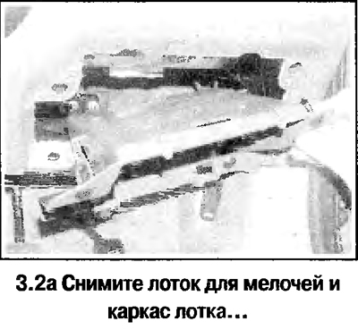
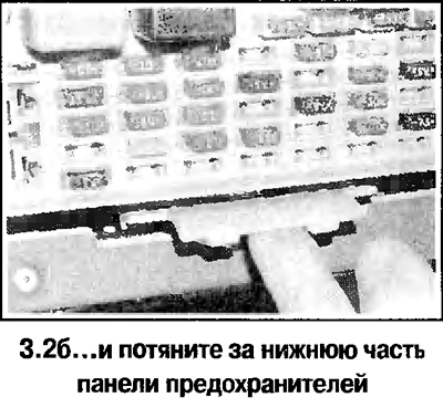
2. The main fuses are located in the driver's side panel under the trim panels. To access the fuse…


2. The main fuses are located in the driver's side panel under the trim panels. To access the fuse…


Fuses


Fuses are designed to break the circuit when the current reaches a certain value, in order to protect elements and wires that could be damaged by too much current. A sharp increase in current is usually caused by a fault in the circuit, most often a short circuit.


Most of the fuses are located in the fuse box on the left side of the instrument panel, with additional fuses located in the fuse and relay box on the right side of the engine compartment. On later models, one or three additional high-power fuses may be installed in the engine compartment, near the battery. On models with one fuse located near the battery, it protects the anti-lock brake system circuits. If three fuses are installed, the two fuses located closest to the battery protect the charging system circuit, and the third fuse located farthest from the battery protects the anti-lock brake system circuits.

To access the fuse box on the instrument panel, open the cover. To access the fuses located in the fuse box in the engine compartment, simply remove the cover (see photo).

The designations of the circuits protected by the fuses are indicated on the fuse box cover.

Before removing a fuse, turn off the corresponding circuit (or ignition), then remove the fuse from the contacts. The wire should be visible inside the fuse; if the fuse is blown, the wire will be broken or melted.

Always use fuses of the correct rating. Never use a fuse of a different rating or replace it with something else. Do not replace a fuse more than once without eliminating the source of the fault. The fuse rating is indicated on the top of the fuse; please note that the fuses are color coded for easy identification

If a fuse blows immediately after replacement, do not replace it again until you have installed and corrected the cause of the fault. In most cases, the cause of the fault is a short circuit caused by poor insulation. If the fuse protects several circuits, try to find the circuit that is causing the fuse to blow by turning on each circuit in turn (if possible). Always keep a set of spare fuses of different ratings in your car. They should be secured to the base of the fuse box.


Relay


A relay is an electronic switch that is used for the following reasons:
  • a) The relay can switch high voltage current without being in the circuit through which that current flows, and this allows the use of thinner wires and contacts.
  • b) A relay can have more than one control source, unlike a mechanical switch.
  • c) The relay may have a timer function - for example, a relay used for intermittent operation of windscreen wipers.

Most relays are located in the fuse box in the engine compartment or behind the lower trim panel of the instrument panel on the passenger side. Depending on the engine type, year, and equipment installed, additional individual relays may be installed in the engine compartment and various other locations in the vehicle.

If a circuit or system controlled by a relay fails and you suspect the relay is at fault, turn on the system. If the relay is working, you should hear a click when power is applied to it, in which case the source of the fault is another element of the system or the connecting wires. If the relay does not come on, then either the relay is not receiving power or switching voltage, or the relay itself is faulty. Relays are tested by replacing them with a working relay. Be careful when doing this, because although some relays look and function the same, there are relays that look similar but function differently.

Before removing the relay, first check that the ignition is off. Then you can simply take the relay out of the socket and insert a new one in its place.


3. The protected circuits are designated by mnemonic symbols (see photo).
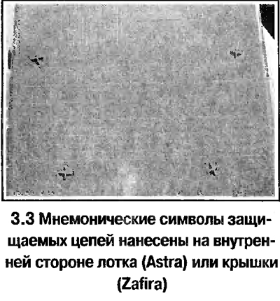
3. The protected circuits are designated by mnemonic symbols (see photo).


4. A blown fuse can be identified by the melted current filament.

5. Before replacing a fuse, make sure the circuit is disconnected. Remove the fuse (see photo).
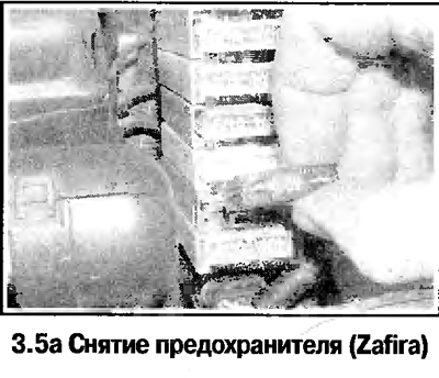
5. Before replacing a fuse, make sure the circuit is disconnected. Remove the fuse (see photo).
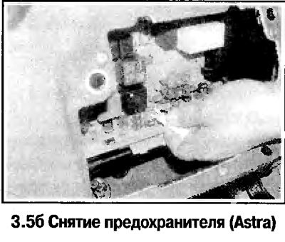

5. Before replacing a fuse, make sure the circuit is disconnected. Remove the fuse (see photo).


6. Before replacing, determine the cause of the burnout and eliminate it. The new fuse must be fully compatible with the one being replaced.


7. The rated current of the fuse can be determined by the color marking.

8. A spare fuse is located in the clips in the fuse panel.

Relay


9. The electrical system uses relays that are used both for closing and opening circuits with high current and for operating in timer mode (for example in the windshield wiper/washer circuit).

10. The main relays are mounted on the fuse panel on the left side of the engine compartment (see photo).
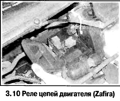
10. The main relays are mounted on the fuse panel on the left side of the engine compartment (see…


11. If, when the circuit controlled by the relay fails, characteristic clicks are not heard, then the relay itself is faulty. Otherwise, you should look for a fault either in the circuit itself or in the relay control circuit. In this case, it is recommended to replace the relay with a known good one that exactly matches the one being replaced.

12. The relay is removed from the socket on the panel (see photo). Before removing the relay, disconnect the corresponding circuit.
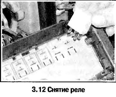
12. The relay is removed from the socket on the panel (see photo). Before removing the relay,…


13. The main fuse box has a timer (mounted on skids), which combines several relays.


This article is available at russian, bulgarian, belarusian, ukrainian, serbian, croatian, romanian, polish, slovak, hungarian
Checking the article: Kornev Georgy

Share information:

Previous articles
Opel Astra G: Equipment and devices
Next articles

Finding the source of a fault in an electrical system — general description
General information
Technical data
Switches — Removal and Installation
Outdoor Lighting Lamps — Removal and Installation
Interior Lighting Lamps — Removal and Installation
Outdoor lighting fixtures — removal and installation
Headlight Beam Adjustment — General Information
Instrument cluster — removal and installation


See similar ones from other Opel car manuals:
▶ Fuses and relays — location and designation Opel Corsa C (2000-2006)
▶ Fuses and relays — general description Opel Omega A (1986-1993)
▶ Fuses and Relays — General Description Opel Vectra A (1988-1995, petrol)
▶ Mounting Blocks — Replacing Fuses and Relays Opel Zafira A (1999-2005, petrol)
▶ Relays and Fuses Opel Vivaro A (2001-2014)
Link to this page in different formats

Visitor comments


No comments yet


How much will 47 + 15 =


Astra J (2009-2015, petrol) 
  • General information
  • Vehicle device
  • User manual
  • Faults en route
  • Maintenance
  • Power unit
  • Engine repair
  • Cooling and lubrication system
  • Engine power system
  • Exhaust system
  • Transmission
  • Clutch
  • Car gearbox
  • Drive shafts
  • Chassis
  • Front suspension
  • Rear suspension
  • Steering
  • Brake system
  • Wheels and tires
  • Body
  • Exterior
  • Interior
  • Doors and windows
  • Body Care
  • Heating and air conditioning
  • Security systems
  • Electrical equipment
  • Equipment and devices
  • Lighting and signaling
  • Power devices
  • Electrical circuits
Astra H (2004-2009) 
  • General information
  • Introduction to the guide
  • Troubleshooting
  • User manual
  • Maintenance
  • Power unit
  • Engine repair
  • Cooling and heating
  • Power and exhaust system
  • Ignition system
  • Launch and charge system
  • Transmission
  • Mechanical gearbox
  • Automatic gearbox
  • Drive shafts
  • Chassis
  • Brake system
  • Car suspension
  • Steering
  • Body
  • Interior
  • Exterior
  • Electrical equipment
  • Equipment and devices
  • Electrical circuits
Astra G (1998-2004) 
  • General information
  • Introduction to manual
  • User manual
  • Maintenance
  • Power unit
  • SOHC gasoline engines
  • DOHC gasoline engines
  • Diesel engines 1.7 and 2.0
  • Engine repair
  • Cooling system
  • Supply system
  • Injection system (gasoline)
  • Injection system (diesel)
  • Exhaust system
  • Charge and launch system
  • Ignition system (gasoline)
  • Preheat system (diesel)
  • Transmission
  • Manual gearbox
  • Automatic gearbox
  • Clutch
  • Drive shafts
  • Chassis
  • Brake system
  • Wheel suspension
  • Steering
  • Body
  • Exterior
  • Interior
  • Doors and windows
  • Ventilation and heating
  • Electrical equipment
  • Equipment and devices
  • Electrical circuits
Astra G (1998-2004, petrol) 
  • General information
  • User manual
  • Car care
  • Maintenance
  • Power unit
  • Single shaft engines
  • Twin shaft engines
  • Engine repair
  • Cooling and heating
  • Fuel and exhaust systems
  • Starting and charging system
  • Ignition system
  • Transmission
  • Clutch
  • Mechanical gearbox
  • Automatic gearbox
  • Drive shafts
  • Chassis
  • Brake system
  • Car suspension
  • Steering
  • Body
  • Interior
  • Exterior
  • Electrical equipment
  • Equipment and devices
  • Wiring diagrams Opel Astra
  • Wiring diagrams Opel Zafira
Astra F (1991-1998, petrol) 
  • General information
  • Maintenance
  • Power unit
  • Engine in car
  • Engine removed
  • Cooling system
  • Heating and ventilation
  • Fuel supply (carburetor)
  • Fuel supply (injector)
  • Emission control
  • Ignition system
  • Transmission
  • Clutch
  • Mechanical gearbox
  • Automatic gearbox
  • Drive shafts
  • Chassis
  • Brake system
  • Car suspension
  • Steering
  • Body
  • Exterior
  • Interior
  • Electrical equipment
  • Equipment and devices
  • Electrical circuits
OpelBook.ru © 2017–2026 · Mobile version · · Sitemap: EN BG BY UA RS HR RO PL SK HU · Feedback · Site search
Astra F, petrol · Astra G, petrol · Astra G · Astra H · Astra J, petrol · Corsa B · Corsa C, petrol · Corsa C · Insignia A · Kadett D · Kadett E · Omega A · Omega B · Omega B2 · Vectra A, petrol · Vectra A · Vectra B, petrol · Vectra B · Vectra C · Zafira A, petrol · Frontera A, petrol · Frontera B · Ascona C · Vivaro A ·
We want your visit to be comfortable 🤝! We use cookies 🍪 to make that happen.