
All engines except 1.6L engine with multiport fuel injection.
Removing
The coil is installed on the left side of the engine compartment, in front of the suspension strut.
Disconnect the negative battery terminal.
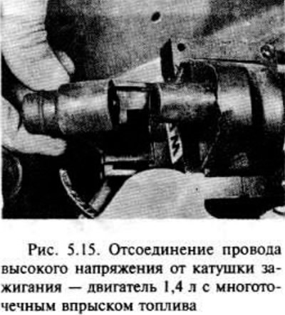
Disconnect the HV wire from the coil (pic. 5.15).
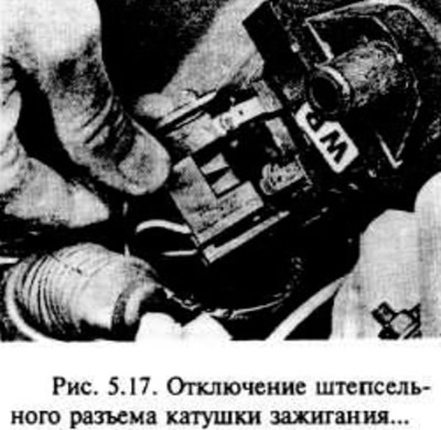
Disconnect the LV wires from the coil and/or the coil connector (pic. 5.17).
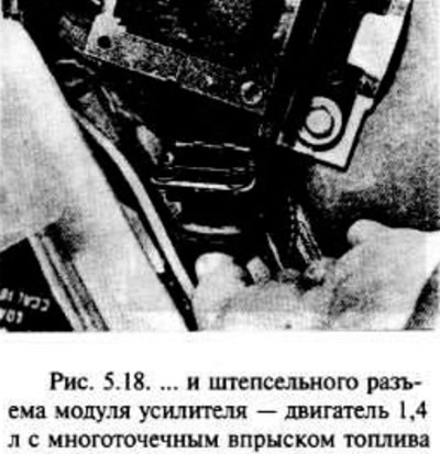
If required, disconnect the plug connector from the ignition amplifier module located under the coil (pic. 5.18).
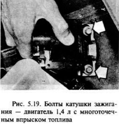
Remove the two coil bolts and remove it along with the amplifier module and mounting plate where required (pic. 5.19). On some models equipped with power steering, one of the coil bolts also secures the power steering fluid reservoir mounting bracket. Also note the location of the coil suppressor, which can be secured with one of the screws.
If required, disconnect the coil from the amplifier module mounting plate.
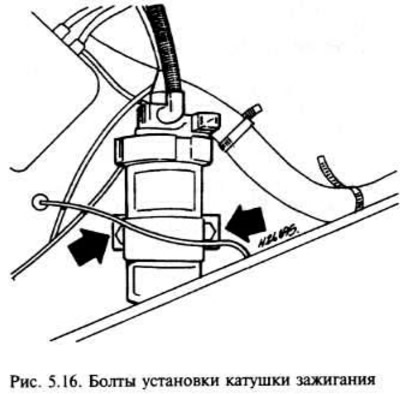
On models with a cylindrical coil, you can remove the clamp from the coil by unscrewing its nut (pic. 5.16).
Examination
Connect an ohmmeter between the two LV terminals and check the primary winding for continuity. Connect an ohmmeter between the HV terminal and the LV terminal and check the integrity of the secondary winding. If there is a defect, the coil should be replaced.
Using an ohmmeter or tester, check that there is no connection between the HH terminal and the coil body. If there is, the coil should be replaced.
Installation
Installation is in the reverse order of removal, but make sure that (If you want to) the coil suppressor is in place before putting the coil bolts. Check the correct connection of all wires and their reliability.
1.6L engine with multipoint fuel injection
Removing
The ignition coil is installed on the left side of the camshaft housing, in the place where the ignition distributor would normally be.
Disconnect the negative battery terminal.
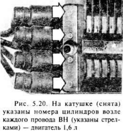
Disconnect the HV wires from the coil, noting their location. Remember that the cylinder numbers are marked on the ignition coil housing near each contact (pic. 5.20).
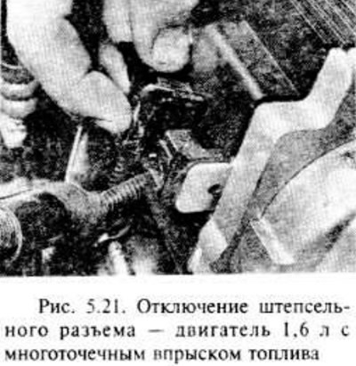
Disconnect the coil connector (pic. 5.21).
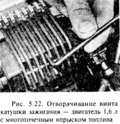
Loosen the three Tox cap screws and remove the coil from its mounting plate (pic. 5.22).
Examination
The design of the coil requires testing by the appropriate equipment of the company.
Installation
Installation is carried out in the reverse order of removal.
Visitor comments