


Headlight range control
By inserting a small screwdriver into slot 2, detach the control unit holder (figure 9.41). Disconnect the wiring connector and then remove the control unit from the holder.
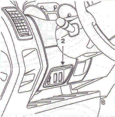
Figure 9.41. Removing and installing the headlight range adjuster.
Headlight range adjuster contact assignment
The purpose of the contacts of the headlight beam angle adjuster is shown in the figure 9.42.
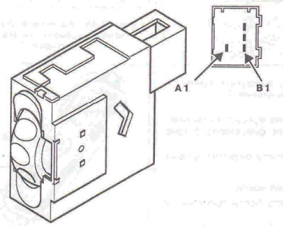
Figure 9.42. Headlight beam angle adjuster contacts assignment: A1 - "+" after ignition switch; B1-Connection to "ground"; B2 - Low beam headlight signal; VZ - Output of the control signal.
Regulator position "0" - output control signal voltage is 11 V.
Regulator position "1" - output control signal voltage is 8.5 V.
Regulator position "2" - output control signal voltage is 6 V.
Regulator position "3" - output control signal voltage 3.5 V.
(Material published on the website: opelbook)
Regulator position "4" - output control signal voltage 1.1 V.
Visitor comments