
The ignition system consists of a primary low voltage circuit (LT) and secondary high voltage circuit (NT). When the ignition is turned on, current is applied to the primary winding of the ignition coil, and a magnetic field appears. At the right moment of ignition, the low voltage circuit is broken electronically by a sensor disk attached to the crankshaft. The magnetic field drops and a current is induced in the secondary high-voltage winding. This high voltage is applied through the distributor runner to the appropriate spark plug. After the ignition spark is applied, the low voltage circuit is activated again and the cycle repeats.
The ignition timing is controlled by a microprocessor in the control unit. On 1.8 models, the control unit is located in the right rear corner of the engine compartment, and on carburetor models, a vacuum hose is attached to it. On 2.0 models, the control unit is integral with the Motronic engine control unit located on the right side in the driver's foot area. The control unit receives information about the engine speed, load and temperature and, based on these data, determines the correct ignition timing.
Note: When working on an ignition system, remember that high voltage can be significantly higher than on a conventional system and in some cases can be fatal.
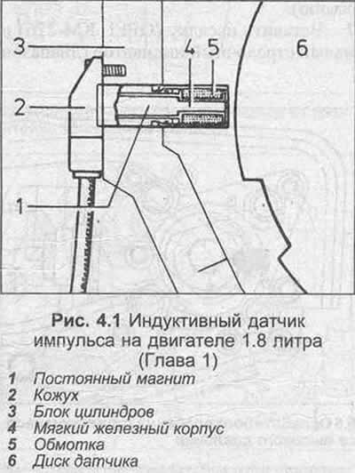
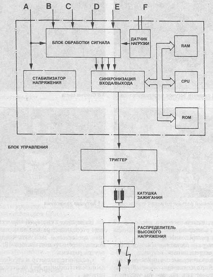
Pic. 4.3 Components of the ignition system on 1.8 liter carburetor engines (Chapter 1)
A - Battery voltage
B - Resistance code (octane number)
C - Cooling temperature. liquids
D - Engine speed
E - Throttle switch position
F - Intake manifold vacuum
CPU - Control Processor (microprocessor)
RAM (RAM)
ROM - ROM (permanent memory) (program memory)
I/O
Visitor comments