
Note: Upper bearing replacement can be done without removing the entire column, however it must be removed to replace the lower bushing.
1. Remove the steering wheel as described in Chapter 21.
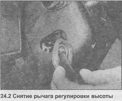
2. Unscrew the manual steering wheel height adjustment lever (photo).
3. Remove screws and separate covers of a casing from a steering column.
4. Set the ignition key to position II, press the small detent and pull out the lock cylinder spring.
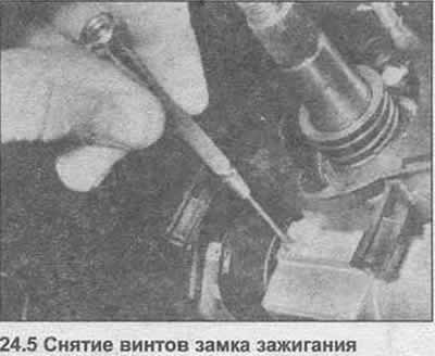
5. Disconnect the ignition switch wire connector, then unscrew the two screws and remove the ignition switch (photo).
6. Using a socket wrench, remove the switch housing mounting bolts.
7. Press the plastic clips and remove the turn signal switch and wiper switch. It is not necessary to disconnect the switch wiring.
8. For further dismantling, remove the column assembly and remove the rubber protective boot.
9. To replace the lower bushing, press the two plastic tabs and pull the bushing off the lower end of the inner column. Fill the inside of the new bushing with multipurpose lubricant and install it on the outer column with the long seal lip facing down.
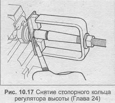
10. To remove the height adjuster mechanism, compress the top spring to remove the retaining ring. A special tool for this is shown in Fig. 10.17 and a similar tool can be made using a metal plate and the available steering wheel lock nut.
11. With the circlip removed, remove the slip ring, spring, o-ring, and support ring.
12. Compress the height adjustment spring and remove. The spring is very tight, so be careful.
13. Pull out the pivot pins and remove the bearing housing.
14. If necessary, the steering column lock cover can be removed by drilling shear bolts. Coat the threads of the new bolts with blocking fluid, install a new shroud, and tighten the bolts until the heads shear off. Note that ball bearings cannot be replaced separately from the housing.
15. Remove the adjustment lever and detent lever from the bearing housing.
16. If necessary, separate the halves of the universal joint.
17. Installation is carried out in reverse order, considering the following:
- a) After assembling the halves of the hinge pins, they must be fixed at three points.
- b) After assembling the steering lock cover, check the gap between the two stopper buffers and the cover.
- c) If the entire steering column was removed, follow the instructions given in Chapter 22, paragraph 12 when installing.
Visitor comments