
2. Clean the working surfaces of the brake disc with methyl alcohol.
3. Check the working surfaces of the brake disc for the following defects:
- Rust and/or pitting. A light layer of rust can be removed with sandpaper. Large amounts of rust and/or pitting should be removed by regrinding the disc.
- Cracks.
- Iridescent spots due to overheating.
4. If the working surfaces of the brake disc have one or more of the listed defects, the disc requires regrinding or replacement.
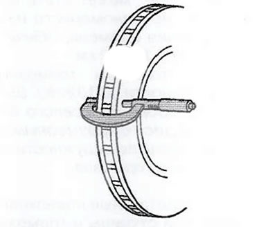
5. Using a micrometer calibrated to thousandths of a millimeter, measure the wear depth of the working surface of the brake disc.
6. Compare the obtained wear value with the specification: maximum allowable wear of the brake discs: 1.50 mm.
7. If the wear of the brake disc exceeds the specified value or uneven wear is observed, the brake disc must be reground or replaced with a new one.
8. Measure the thickness of the brake disc at four points equidistant from each other along the circumference of the disc. Make sure that the thickness of the disc is measured only in the working areas and at the same distance from the edge of the disc (about 13 mm) for each dimension.
9. Compare the minimum measurement value with the specification:
- Maximum allowable minimum thickness after grinding: 28 mm.
- Brake disc culling thickness: 27 mm.
10. Calculate the circumferential thickness change of the brake disc and compare it with the specification: the maximum allowable change in the circumferential thickness of the brake disc: 0.025 mm.
Note.
- A brake disc whose thickness variation exceeds the maximum allowable value must be reground or replaced. A brake disc with excessive circumferential thickness variation causes brake pulsation.
- After each replacement or regrinding of the brake disc, the axial runout of the brake disc must be measured to ensure optimum brake performance.
11. If the thickness of the brake disc changes beyond the allowable value, the brake disc must be reground or replaced with a new one.
Note.
- After each replacement or regrinding of the brake disc, the axial runout of the brake disc must be measured to ensure optimum brake performance.
- Axial runout of the installed brake disc that exceeds the allowable value can cause the development of uneven disc wear over time, usually in the range of 4800-11300 km.
- Changing the circumferential thickness of the brake disc must be carried out before checking the axial runout. A brake disc with excessive circumferential thickness variation causes brake pulsation.
12. Check the contact surfaces of the wheel hub flange and the brake disc to ensure that there are no foreign particles, corrosion or rust. If any of the listed contaminants are found, the following must be done:
- Thoroughly clean all dirt from the contact surfaces of the wheel hub and brake disc.
- Clean the working surfaces of the brake disc with methanol.
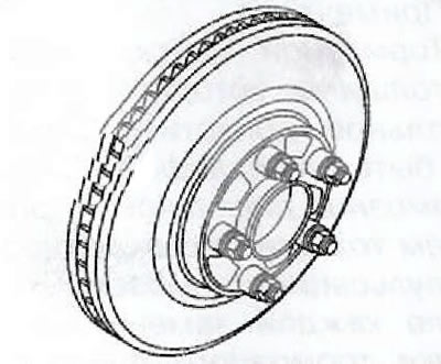
13. Install the brake disc on the wheel hub, guided by the marks made during removal.
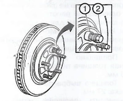
14. Securely fix the brake disc on the wheel hub flange and install one of the wheel nuts (2) on top pin (1).
15. While still holding the brake disc, hand-tighten the wheel nut until
16. Install the remaining wheel nuts onto the studs and hand-tighten in sequence «star».
17. Tighten the wheel nuts to the specified torque to secure the rotor properly.
18. If the brake disc has been reground or replaced, go to step 24.
19. If the brake disc meets the following criteria, go to step 20:
- The parameters of the brake disc correspond to the specification and the disc is reused.
- The brake disc has not been resurfaced.
- The change in the thickness of the brake disc around the circumference does not exceed the maximum allowable value.
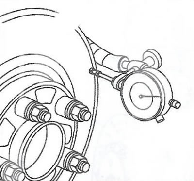
20. Install a GE-571-B dial indicator or equivalent on the steering knuckle and place the indicator probe perpendicular to the working surface of the brake disc approximately 13mm from the outer edge of the disc.
21. Measure and record the value of the axial runout of the brake disc:
- Rotate the brake disc until the minimum value is displayed, then reset the dial indicator to zero.
- Turn the brake disc until the maximum value is displayed on the dial gauge.
- Mark the position of the brake disc relative to the wheel studs, corresponding to the maximum value on the dial gauge.
- Write down the obtained value of the axial runout of the brake disc.
22. Compare the obtained value of the axial runout of the brake disc with the specification: maximum allowable runout of the brake disc (front/rear): 0.05 mm.
23. If the brake disc runout is within specification, go to step 28. If the brake disc axial runout is greater than the specified value, regrind the disc until the surfaces are parallel. Once the disc has been sanded, go to step 24.
24. Install a dial indicator GE-571-B or similar on the steering knuckle and place the indicator probe perpendicular to the working surface of the brake disc approximately 13 mm from the outer edge of the disc.
25. Measure and record the value of the axial runout of the brake disc:
- Rotate the brake disc until the minimum value is displayed, then reset the dial indicator to zero.
- Turn the brake disc until the maximum value is displayed on the dial gauge.
- Mark the position of the brake disc relative to the wheel studs, corresponding to the maximum value on the dial gauge.
- Write down the obtained value of the axial runout of the brake disc.
26. Compare the obtained value of the axial runout of the brake disc with the specification: maximum allowable runout of the brake disc (front/rear): 0.05 mm.
27. If the obtained value of the axial runout of the brake disc exceeds the set value, replace the brake disc with a new one.
28. If the obtained value of the axial runout of the brake disc is correct, install the brake disc with caliper, then depress the brake pedal several times to fix the brake disc in place before unscrewing the wheel nuts.
Visitor comments