


In this section, the design and repair of some units and systems are described using the example of the engine mod. A16 XER (115 hp). The other engines are similar in design. Features of turbocharged engines are described in the subsection Design Features of Turbocharged Engines.
Cylinder head the engine is made of aluminum alloy with a transverse cylinder scavenging scheme (the inlet and outlet ports are located on opposite sides of the head), valve seats and guide bushings are pressed into the head. Each inlet and outlet valve is equipped with one spring, fixed through the plate with two crackers.
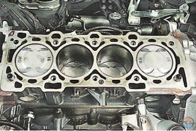
Cylinder block the engine block is a single casting that forms the cylinders, cooling jacket, upper part of the crankcase and five crankshaft supports, made in the form of crankcase partitions. The block is made of special high-strength cast iron with cylinders bored directly in the block body. The engine main bearing caps are machined together with the blocks and are therefore not interchangeable. The cylinder block has special bosses, flanges and holes for fastening parts, units and assemblies, as well as channels for the main oil line.
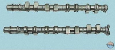
Camshafts cast, cast iron, equipped with synchronization rotors that ensure the operation of the camshaft position sensors. Inlet and outlet valve drive shafts are provided with oil channels through which oil is supplied under pressure to the mechanisms of the variable valve timing system.
Crankshaft, forged from special steel, rotates in main bearings with thin-walled steel liners with an antifriction layer of aluminum-tin alloy. The axial movement of the crankshaft is limited by special flanges made on the middle main journal and resting on the flanges of the thicker liners of the middle main bearing.
(Source is on the website: www.opelbook.ru)
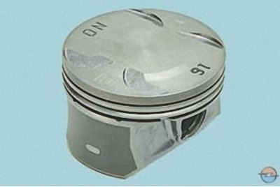
Pistons made of aluminum alloy.
The cylindrical surface of the piston head has annular grooves for the oil scraper and compression rings. The engine pistons are additionally cooled by oil supplied through an opening in the upper head of the connecting rod and splashed onto the piston bottom.
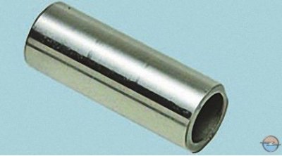
Piston pins they are installed in the piston bosses with a gap and are pressed with tension into the upper heads of the connecting rods, which are connected with their lower heads to the connecting rod journals of the crankshaft through thin-walled liners, the design of which is similar to the design of the main ones.
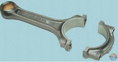
Connecting rods steel, forged, with an I-section rod.
Lubrication system combined (for more details see. Lubrication system).
Crankcase ventilation system closed type does not communicate directly with the atmosphere, therefore, simultaneously with the suction of gases and gasoline vapors, a vacuum is formed in the crankcase in all engine operating modes, which increases the reliability of various engine seals and reduces the emission of toxic substances into the atmosphere.
Cooling system engines, hermetically sealed, with an expansion tank, consists of a cooling jacket made in casting and surrounding the cylinders in the block, combustion chambers and gas channels in the cylinder head. Forced circulation of the coolant is provided by a centrifugal water pump driven by a crankshaft poly-V belt for auxiliary drives. To maintain the normal operating temperature of the coolant, a thermostat is installed in the cooling system, blocking a large circle of the system when the engine is not warmed up and the coolant temperature is low.
Power supply system the engine consists of an electric fuel pump installed in the fuel tank, a throttle assembly, a fine fuel filter, a fuel pressure regulator, injectors and fuel lines, and also includes an air filter.
Variable valve timing system dynamically adjusts the position of the intake and exhaust camshafts. This system allows you to set the optimal valve timing for each moment of engine operation, which results in increased power, better fuel economy and lower toxicity of exhaust gases. The system mechanism is connected by channels in the cylinder head and in the camshafts with electromagnetic valves. These valves hydraulically control the mechanism of the variable valve timing system. The electromagnetic valves, in turn, are controlled by the electronic engine control unit.
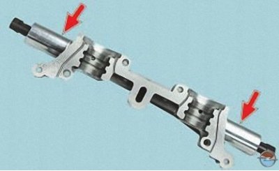
A solenoid valve consisting of an electromagnet and a valve (the latter, in turn, consists of a valve and a spring), based on signals from the electronic engine control unit, supplies oil under pressure from the main line of the lubrication system to one of the working cavities of the variable valve timing system mechanism and drains oil from the other cavity, which leads to mutual movement of the mechanism elements and, as a consequence, to a dynamic change in the position of the intake and exhaust camshafts.
When the engine is idling, the electronic engine control unit repeatedly activates the electromagnetic valve for short periods of time in order to clean its elements and channels from any contaminants that accidentally get into them.
When the power supply to the electromagnetic valves of the variable valve timing system is disconnected, the oil supply holes from the main line and the drain are completely open and the mechanism is set to its original position. In this case, the engine operates without changing the valve timing.
Visitor comments