
The appearance and location of individual elements in cars of various modifications may differ from those shown in the accompanying illustration.
The location of the controls on the dashboard of the car
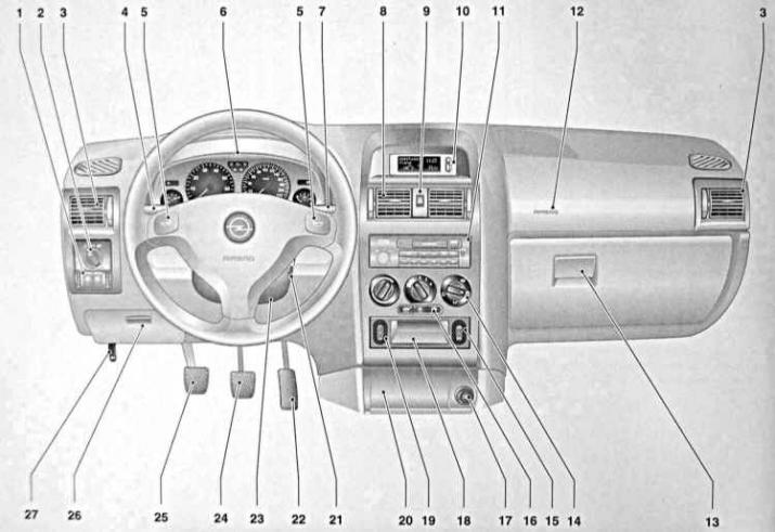
1 - Headlight tilt control, fog lamp and rear fog lamp switches, instrument backlight intensity control
2 - Switch for controlling the operation of external lighting devices / turning on the backlight of devices
3 - Deflectors of the side air ducts of the ventilation / interior heating system
4 - Left stalk switch for controlling the operation of direction indicators, selecting the headlight mode, high beam signaling / controlling the operation of the tempostat
5 - Icons for the horn button designation
6 - Instrument cluster
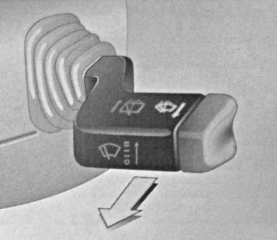
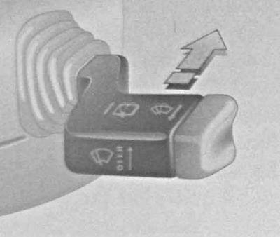
7 - Right stalk switch for controlling the operation of the windshield washers and (with appropriate equipment) headlight lenses / onboard processor mode switch
8 - Deflectors of the central air ducts of the ventilation / interior heating system
9 - Alarm switch
10 - Display of digital clock / outside temperature meter / radio / infotainment system / on-board processor
11 - Radio / infotainment system
12 - Passenger airbag module cover
13 - Glove box
14 - Control panel for the operation of heating / ventilation / air conditioning systems
15 — the Switch of management of functioning of the electric drive of windows (Convertible models)
16 - Switches for selecting air circulation modes and turning on the rear window heating
17 - Cigarette lighter / on-board power outlet
18 - duffel pocket
19 — The switch of management of functioning of the electric drive of a convertible top (Convertible models)
20 - Ashtray
21 - Ignition lock / steering column lock
22 - Gas pedal
23 - Control knob for adjusting the position of the steering column
24 - Brake pedal
25 — Clutch pedal
26 - Glove box / fuse box
27 — The lever of a drive of a release of a latch of the lock of a cowl
The layout of the control lamps / indicator lights and instrumentation on the dashboard of the car
The arrow shows the location of the digital display setting button.
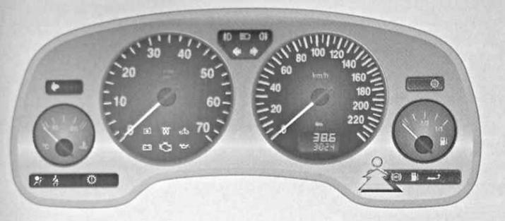
Instrument cluster
Control lamps and light indicators of the panel of devices
The completeness of the instrument panel with control lamps and indicator lights depends on the vehicle modification.
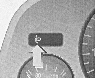
Control lamp for automatic headlight range adjustment
The control lamp is located on the left side of the instrument cluster above the temperature gauge and briefly works when the ignition is turned on and should go out a few seconds after the engine is started. Activation of the control lamp while driving indicates a malfunction of the regulator. To eliminate the reasons for the failure, contact the car service specialists.
Additional security warning lamp (SRS)
This warning lamp serves to alert the driver of failures in the electrical circuits of the SRS additional safety systems (airbags, emergency belt tensioners)
Pilot lamp «Don't forget to fasten your seat belts!»

The short-term operation of the control lamp when the ignition is switched on is accompanied by an audible signal and serves as a warning to the driver and passengers about the need to fasten their seat belts before driving.
Brake / Clutch Warning Light
If the control lamp continues to burn at the included ignition, it is necessary to check completeness of a release of a parking brake. The operation of this lamp may also indicate a drop in the level of the working fluid in the reservoirs of the GTZ or the clutch hydraulic cylinder.
Control lamp of the engine cooling system with electronic control
The control lamp works briefly when the ignition is switched on and should go out a few seconds after the engine is started. Activation of the lamp while driving indicates a malfunction in the engine cooling circuit or air conditioning circuit. The electronic control system automatically switches to emergency mode of operation, which allows you to continue driving. Check coolant level (see chapter Current service). To eliminate the reasons for the failure, contact the car service specialists.
Control lamp of the engine preheater (diesel models)
The activation of this warning lamp occurs only when the preheating system of the diesel engine is activated at low ambient temperatures.
Control lamp of electronic control systems of the engine / automatic transmission / blocking of start
The control lamp works briefly when the ignition is switched on and should go out a few seconds after the engine is started. Failure of the lamp to turn off indicates a malfunction in the electronic engine control system or AT. At the same time, the control system automatically switches to emergency operation mode, which may be accompanied by a certain increase in fuel consumption and a decrease in the power developed by the engine. Seek help from car service specialists.
In some cases, troubleshooting can be achieved by turning off the ignition and trying to start the engine again.
If, when the ignition is turned on, the lamp starts to function in a flashing mode, therefore, there is a violation in the engine blocking system, turn the ignition key to the extreme left position, remove it from the lock, then insert it again and try again. If necessary, try using a spare key, or contact a car service specialist for help.
charge control lamp
The control lamp works briefly when the ignition is switched on and should go out a few seconds after the engine is started. Failure of the lamp to turn off indicates a malfunction in the charge system. Stop driving and turn off the ignition. Check the tension of the alternator drive belt, the reliability of the terminal connections of the generator wiring, and the tightness of the alternator mounting bolts.
On models equipped with Z12XE, Y20DTL, Y20DTH and Y22DTR engines, it is also possible that the cooling system of the power unit will malfunction. If necessary, seek help from a car service specialist.
Engine failure warning lamp («Check engine» / MIL)
The control lamp works briefly when the ignition is switched on and should go out a few seconds after the engine is started. Failure of the lamp to turn off indicates a malfunction of the engine or a malfunction in the functioning of any of the components of the exhaust gas toxicity reduction systems. Try to avoid sudden increases in speed and high engine speeds during further movement. At the first opportunity, seek help from car service specialists.
Turning on the lamp in flashing mode while driving warns the driver of a failure that can lead to failure of the catalytic converter, you should immediately seek help from the nearest workshop.
Oil pressure warning lamp

The control lamp works briefly when the ignition is switched on and should go out a few seconds after the engine is started. Short-term operation of the lamp is also allowed when the engine is idling. If the indicator lamp fails to turn off after the engine is started / it comes on while driving, immediately turn off the engine and check the level and pressure of the engine oil. If necessary, adjust the oil level (see chapter Current service). At the earliest opportunity, have the engine condition diagnosed at a vehicle manufacturer's authorized service station.
Control lamp of activation of fog lamps

The warning lamp is activated when the fog lamps are activated and remains on until the latter are turned off.
Control lamp of activation of high beam of headlights
The indicator has a characteristic purple color of the glow and is activated when the headlights of the car are switched to high beam mode (permanent or signal).
Control lamp of activation of back foggy lanterns

The indicator lamp is activated when the rear fog lamps are activated and remains on until the latter are turned off.
Direction indicators
The activation of the corresponding indicator occurs when the right or left turn indicators are turned on. Turning on the alarm causes both indicators to go on at the same time.
A noticeable increase in the frequency of flashes indicates the failure of any of the direction indicator lamps.
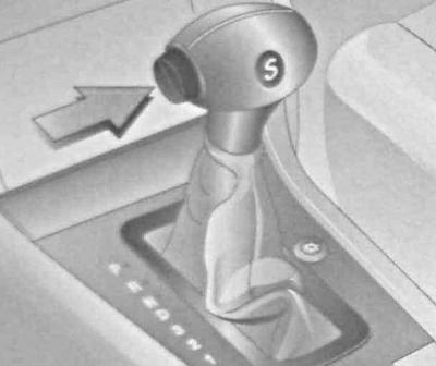
Control lamp of transfer of AT in a sports mode (with appropriate vehicle equipment)
On models of the corresponding configuration, the operation of this control lamp is accompanied by the transfer of the AT to the sport mode.
Control lamp of antiskidding system (TCS) / anti-skid system (ESP)

The control lamp works briefly when the ignition is switched on and should go out a few seconds after the engine is started. Turning off the lamp indicates the transition of the electronic stabilization systems ESP / TCS to the active state. By flashing this warning lamp, the activation of the traction control process when the ESP / TCS systems are activated is confirmed.
The operation of electronic motion stabilization systems may be accompanied by a slight decrease in the power developed by the engine (the noise produced by the engine will change). The possibility of automatic braking of the car is also not excluded.
The ESP system serves to prevent the risk of losing control of the vehicle in emergency situations, and its operation should remind the driver to match the speed limit with the road surface.
Control lamp of system of antiblocking of brakes (ABS)
The control lamp works briefly when the ignition is switched on and should go out a few seconds after the engine is started. Turning off the lamp indicates the completion of the ABS self-diagnosis procedure and the transition of the system to the active state.
The ABS self-diagnosis process may be accompanied by specific sounds. Failure of the lamp to turn off, or its operation while driving, indicates that the self-diagnosis system has detected problems in the ABS circuit. The brake system then switches to normal operation, which means that the movement can continue unhindered. For troubleshooting, contact the specialists of the authorized service station of the vehicle manufacturer for help.
The built-in ABS self-diagnosis system makes it possible to significantly simplify the process of finding and eliminating the causes of system failures.
If the ABS and brake system warning lamps come on at the same time, immediately stop driving, gradually slowing down, remove the vehicle from the stream and park on a safe section of the road. Braking should be done with extreme caution, avoiding sudden pressure on the pedal.
Fuel reserve warning lamp

If this warning lamp comes on continuously, it indicates that the fuel supply is running low and the vehicle should be refueled as soon as possible. The transition of the lamp to flashing mode means that the fuel supply has been completely used up.
Try not to run out of fuel! In particular, this warning applies to diesel models, the removal of air from the power system of which is one of the rather laborious procedures.
Trailer indicator lamp
When towing a trailer, this indicator light flashes when the direction indicators are activated. The flashing frequency of the indicator coincides with the flashing frequency of the main control lamps of the direction indicators. The failure of the lamp of any of the direction indicators on the trailer or car leads to the failure of the indicator operation.
Seat occupancy indicator lamp

The seat occupied indicator lamp is integrated into the front ceiling light assembly.
Installing an Opel baby seat in the right front seat should automatically deactivate the passenger airbag. If the occupancy indicator does not come on when the Danish seat is installed, the child seat must be moved to one of the rear seats. The flashing of the control lamp indicates a violation of the correct installation or malfunction of the child seat transponder - if necessary, contact the specialists of the car manufacturer's authorized service station for help.
Meters and pointers
Tachometer
The tachometer is a measure of the engine speed. The tachometer dial is mounted on the left in the central part of the instrument panel (see illustration The layout of the control lamps / indicator lights and instrumentation on the dashboard of the car) and allows you to determine the speed of the engine crankshaft in revolutions per minute (the reading from the scale should be multiplied by 100). The maximum allowable values are given in Specifications to the head Current service.
Speedometer
The speedometer shows the current speed of the vehicle. The speedometer dial is mounted on the right in the central part of the instrument panel (see illustration The layout of the control lamps / indicator lights and instrumentation on the dashboard of the car).
Odometer
The odometer is used to record the total mileage of the vehicle. The odometer readings are displayed in the lower field of the digital display mounted in the lower part of the speedometer dial (see illustration The layout of the control lamps / indicator lights and instrumentation on the dashboard of the car).
With the ignition off, the total mileage display is switched on by briefly depressing the setting button and remains active for about 15 seconds.
Current mileage counter
The meter is designed to record the current mileage of the car from the moment its own readings were reset to zero. The meter readings are displayed in the upper field of the digital display mounted in the lower part of the speedometer dial (see illustration The layout of the control lamps / indicator lights and instrumentation on the dashboard of the car). Resetting the counter is done by pressing the setting button for 2 seconds with the display of the current mileage activated (models with multifunctional digital display, see below) (see ibid).
Built-in speedometer dial multi-functional digital display
On some models, a multifunctional digital display is mounted in the speedometer dial, which allows you to display in its upper field, in addition to the readings of the current mileage registration counter, additional time of day and indication of service intervals.
Switching between the display modes is done by short pressing the setting button (see illustration The layout of the control lamps / indicator lights and instrumentation on the dashboard of the car).
The brightness of the display indication is regulated by the same knob as the intensity of the instrument illumination (see illustration Location of controls on the dashboard of the car). Adjustment of the chronometer readings is carried out using the same setting button, 2-second squeezing of which in the time indication mode leads to the transition to the first hour readings correction mode (adjusted with a short press of a button), then - after the next 2-second holding of the button - minute. The adjustment mode is also exited by holding down the setting button for 2 seconds.
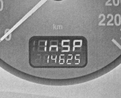
If, when the ignition is switched on, the upper field of the multifunction digital display shows 1_SP, therefore, within one week, or after no more than 500 km of run, the next service of the car should be performed.
Periods of vehicle downtime with a disconnected battery are not counted by the service interval recorder.
Engine coolant temperature gauge
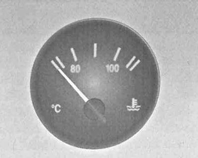
The engine coolant temperature gauge is mounted on the left side of the instrument panel and serves to monitor the temperature characteristics of the power unit.
For structural reasons, the coolant temperature can only be monitored at its level in the system. The output of the engine in the normal operating temperature mode is confirmed by the transition of the pointer to the middle position (between 80 and 100).
When the engine is running, the cooling system is under excess pressure, so the meter readings may briefly rise above 100°C. The shift of the arrow to the scale range highlighted in red indicates overheating - you should immediately stop driving, turn off the engine and check the coolant level (if necessary, make the appropriate adjustment, - see the Head Routine maintenance). Another cause of overheating may be the failure of the cooling fan to operate - check the proper operation of the corresponding sensor-switch.
Fuel gauge
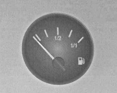
The fuel gauge is located on the right side of the instrument panel. After the fuel tank is completely filled, the pointer arrow leaves the position corresponding to the maximum filling only after a certain vehicle mileage. When the pointer is lowered into the limits of the measuring scale highlighted in red / the fuel reserve warning lamp comes on, the vehicle should be refueled as soon as possible.
Try not to run out of fuel! In particular, this warning applies to diesel models, the removal of air from the power system of which is one of the rather laborious procedures.
Due to the fact that there is always a certain amount of fuel left in the tank, the actual volume of a full refueling may slightly deviate from the nominal value.
Controls located on the instrument panel and steering column
Switch for controlling the functioning of external lighting / running lights / instrument lighting
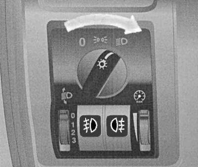
o - Off
With this switch (see illustration The location of the controls on the dashboard of the car and Appearance of the switch for controlling the functioning of external lighting devices / running lights / instrument lighting) the running gear is turned on, as well as the illumination of the instrument panel. In position 0 of the rotary knob of the switch, all exterior lights and instrument panel lights remain off.
On models equipped with daytime running lights (DRL) when the ignition is on and the switch handle is in position 0, the headlights are automatically switched to low beam mode, the instrument lighting is not activated.
When the handle is moved to the middle position, the side lights and rear license plate lights are turned on, and the instrument panel and functional cabin switches are illuminated.
To switch the headlights of the car to the low beam mode, turn the switch handle to the extreme right position.
Switching the headlights to constant high beam mode using the left steering column switch (see below) can only be carried out in this position of the rotary handle.
Pulling the rotary handle towards you forces the interior lighting to turn on.
Adjusting the brightness of the backlight of devices is carried out using the switch mounted on the right under the handle and marked with a pictogram in the form of a symbolic image of a dial meter of a wheel-lever potentiometer (see illustration Appearance of the switch for controlling the functioning of external lighting devices / running lights / instrument lighting).
Fog lamp and rear fog lamp switches
The fog lamp and rear fog lamp function control pushbuttons are located directly below the exterior lighting control switch handle, between the instrument illumination intensity wheel potentiometer and the headlight beam tilt control (see illustration Appearance of the switch for controlling the functioning of external lighting devices / running lights / instrument lighting).

This button turns the fog lights on and off.
When the headlights are switched on, the control lamp mounted in the switch button is activated.

This button is for turning on/off the rear fog lamps.
When the lamps are switched on, the control lamp mounted in the switch button is activated.
Headlight optics direction adjuster
The toggle switch is mounted on the left under the handle of the switch for controlling the operation of external lighting devices (see illustration Appearance of the switch for controlling the functioning of external lighting devices / running lights / instrument lighting) and marked with an icon at the top.
Adjustment is made by transferring the switch lever to one of the four regular positions with the dipped headlights on. With the correct adjustment of the inclination of the headlights relative to the body, the risk of blinding drivers of oncoming and passing vehicles is eliminated.
The adjustment scheme is presented in Specifications at the beginning of the chapter. Failures in the operation of the headlight position correctors are warned by the operation of a special control lamp mounted in the instrument cluster above the temperature meter assembly.
Depending on the vehicle's configuration, the range of tilt of the optical axes of the headlights between positions 2 and 3 of the switch can be very narrow.
Left stalk switch
Using the left steering column switch, the mode of operation of the headlights is selected (low/high beam), the high-beam signaling is carried out, and the direction indicators are also activated.
in normal position (closer to the steering wheel) switch lever headlights are in low beam mode (with the corresponding position of the rotary handle of the switch for controlling the operation of external lighting devices - see above p. Switch for controlling the functioning of external lighting / running lights / instrument lighting). To switch the headlights to the high beam mode, press the switch lever away from you, moving it to the second stationary position - the corresponding control lamp will work on the instrument panel (see above p. Control lamp of activation of high beam of headlights). Switch reset (normal) position turns off the high beam and switches the headlights to low beam.
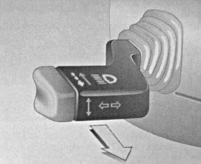
To briefly turn on the high beam headlights in order to give a light signal, pull the lever of the left stalk switch towards you.
High beam signaling can be done in any position of the rotary handle of the switch for controlling the operation of external lighting devices (see the illustration of the appearance of the switch for controlling the operation of outdoor lighting devices/ running lights/ instrument lights).
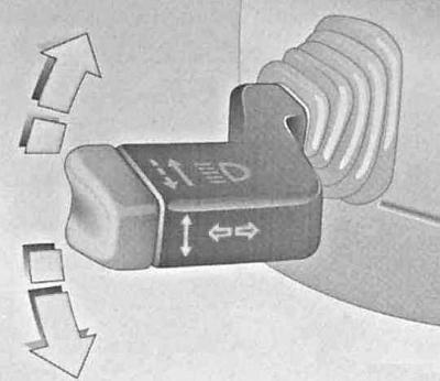
Moving the left stalk lever to the upper or lower stationary position (click) leads to the activation of the corresponding turn indicators.
Disabling direction indicators with the return of the lever to neutral (average) position occurs automatically when the steering wheel is returned to the straight-ahead position. There is also the possibility of short-term inclusion of pointers (for example, to warn of a lane change), - you should move the lever up or down without bringing it to a click, - in this case, the indicators will turn off when the lever is released.
Activation of direction indicators is accompanied by the operation of the corresponding indicator lights on the instrument panel (see above p. Control lamp activation of rear fog lights) and distinct clicks emitted by the interrupter.
Right stalk switch
On models equipped with a multi-functional graphical information display, buttons for switching display modes are mounted in the end of the right stalk lever (see below).
This switch controls the operation of the windshield wipers and the supply of washer fluid.
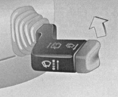
On the models in question, two types of windshield wiper control switches are used: with automatic control (with rain sensor) and without. In both versions, the right stalk lever is capable of moving in a vertical plane with installation in one of four stationary positions, the pictograms corresponding to each of the positions are printed on the front side of the switch. The difference lies in the fact that when the second position of the switch lever is selected from the bottom, in one case the wipers are switched to the normal interval operation mode, in the second, the rain sensor determines the amount of water on the surface of the windshield and automatically adjusts the period of operation of the brushes.
«O» - Windshield wipers off
«–» — Interval / automatic mode of functioning of screen wipers
«–» - Constant low-speed operation of the wipers
«=» - Constant high-speed wiper operation
Pulling the right stalk lever toward you turns on the washer fluid supply to the windshield and headlight lenses (if the latter are enabled). When fluid is applied to the windshield, the wipers perform several work cycles.
Version with automatic control (see above) the washer fluid supply should be periodically turned on in order to keep the working field of the rain sensor clean.
To turn on the rear window wiper/washer on Hatchback and Wagon models, move the right stalk lever away from you. In this case, two operating positions of the lever are provided, in the first of which only the wiper is turned on, in the second (hold the lever fully depressed) in addition, the supply of washer fluid to the glass is activated.
In the first operating position, the rear window wiper will operate in an interval mode with a fixed delay, in the second - continuously.
Hazard switch
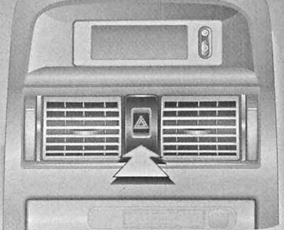
The alarm button switch is located in the central part of the instrument panel between the central air deflector grilles (see illustration The location of the controls on the dashboard of the car). The activation of the alarm leads to the simultaneous activation in the normal flashing mode of all direction indicators, and is also accompanied by the functioning of the corresponding control lamps on the instrument panel and inside the switch button. The frequency of flashing is the same as when the direction indicators are working due to the use of a common breaker.
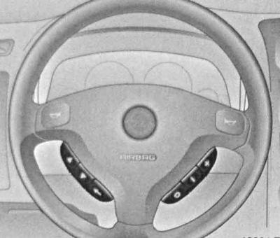
Sound signal
To turn on the sound signal, just press the central steering wheel pad, marked with horn icons.
The switch of heating of back glass and external rear-view mirrors
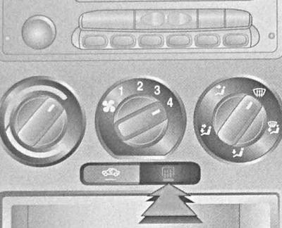
The heated rear window/mirror switch button is mounted on the bottom of the heating/ventilation/air conditioning control panel. The button has a pictogram on the outside, a control lamp is mounted inside, which continues to burn all the time while the heaters remain on.
A timer is mounted in the heater circuit, which automatically turns off the power supply to the heating elements after the control period has expired (15 minutes). This option avoids excessive battery discharge, which is inevitable due to the high energy consumption of the heating elements.
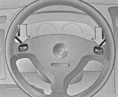
Radio remote control switches
If the vehicle is equipped accordingly, the radio remote control buttons are located on both sides of the steering wheel hub.
 Search for the next active frequency in ascending order
 Search for the next active frequency in descending order
«» - Volume up
«-» - Volume down
«ABOUT» — Switching from radio mode to tape recorder or CD player mode (with appropriate equipment)
Switches of management of functioning of the electric drive of external rear-view mirrors
On models with a manual drive of exterior mirrors, their position is adjusted using the levers located on the inside of the bases of the mirrors - see Elements of vehicle security systems.
On models equipped with an electric drive for adjusting the outside rear-view mirrors, the electric drive operation control switch is located on the inside of the front doors of the car at their junction with the instrument panel. The choice of the mirror to be adjusted is made by moving the upper slide switch to the appropriate side. The actual adjustment is carried out using the lower rotary switch. Do not forget to return the slide switch to the middle after completing the adjustment (neutral) position to avoid the risk of accidentally disturbing the required mirror position.
Visitor comments