


Contents: Keys ⬇ Unlocking and locking doors with a…⬇ Locking doors from the inside ⬇ Additional locking of rear door…⬇ Remote control ⬇ Ignition Switch/Steering Column Lock ⬇ Engine immobilization system ⬇ Enabling/disabling the anti-theft…⬇ Unlocking and locking the…⬇ Hood ⬇ Fully automatic convertible top…⬇ Semi-automatic convertible top…⬇ Installing and removing the…⬇ Electric sunroof ⬇ Window lifters ⬇
Keys
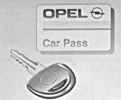
The key is an integral part of the electronic engine immobiliser system. Spare keys ordered from an Opel dealership guarantee trouble-free operation of the electronic engine immobiliser system. This will allow you to avoid unnecessary expenses and possible difficulties in obtaining insurance compensation in the event of damage, as well as problems when making warranty claims.
Keep the spare key in a safe place.
A microchip is built into the key head, which automatically disables the engine immobilization system. If you lose your key, contact the representative office of the car manufacturer.
When using a key equipped with a microchip, some special precautions should be taken:
1. When starting the engine, make sure that the key fob ring and other metal objects do not touch the plastic head of the key;
2. Do not allow the key to come into contact with other microchip-equipped keys that have a microchip with a transceiver installed during engine starting (including keys from other cars);
3. Do not bend the key head and try not to subject the key to impact loads;
4. Do not place the key head in any protective covers that may interfere with the passage of signal pulses;
5. Do not expose the key to high temperatures or direct sunlight for long periods of time;
6. Keep the key dry and do not allow it to come into contact with water or other liquids;
7. Do not leave the key near sources of electromagnetic radiation.
Unlocking and locking doors with a key from outside the car
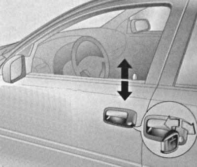
To unlock the car with a key from outside the car, insert the key into the door lock and turn it in the appropriate direction, then pull the handle.
Locking doors from the inside
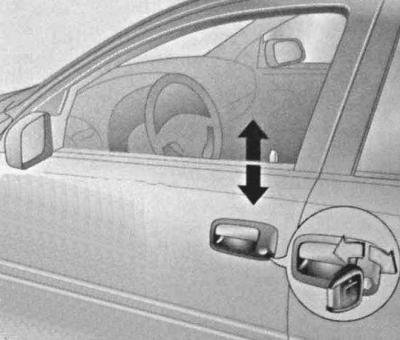
Locking of doors from the inside is done by pressing the push-button switches for locking the locks, built into the upper lower edges of the window openings.
On models equipped with power windows, holding the key in the locked position for a certain period of time should automatically close all open windows, and on Convertible models with a power top, the roof should rise.
Additional locking of rear door locks (Child Lock)
An additional lock is provided to prevent accidental unlocking of the rear doors of the vehicle due to the mischief of children transported in the rear seat.
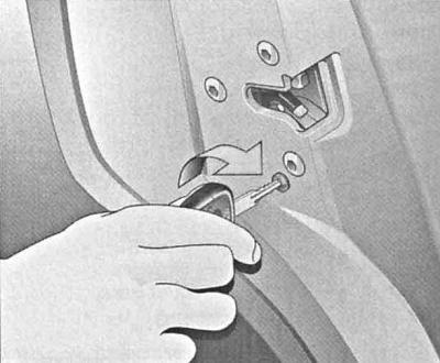
Open the door, insert the key into the lock hole and turn it to the right - after slamming the door can only be opened from the outside.
Remote control
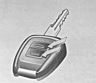
The remote control is built into the key head and allows you to control the operation of a single lock (doors, trunk lid, fuel filler flap), anti-theft alarm and power folding top on Convertible models.
Control of lock actuators
The range of the remote control transmitter is approximately 3 meters and may be reduced by various types of passive or active interference.
When unlocking the doors using the remote control built into the key head, point your hand with the key in it toward the car and press the button. The remote control is functioning properly when the LED built into it lights up. To open the door after the door activators have been triggered, simply pull the handle. The doors are locked by pressing the button.
Avoid exposing the remote control to moisture and direct sunlight.
Failures of the single lock actuators to operate upon command from the remote control can be explained by several reasons:
1. The remote control range has been exceeded - try again from a shorter distance;
2. The internal battery of the remote control is discharged - replace the battery (see below);
3. The transmitter and receiver are out of sync due to frequent use of the remote control from an excessively long distance - re-synchronize (see below);
4. Trying to reactivate the locks after an excessively short period of time - wait at least 30 seconds, then try again;
5. There is active interference associated with the operation of a source of powerful radio emission nearby - try again from a shorter distance, if necessary, unlock the door using the key (see above item. Unlocking and locking doors with a key from outside the car).
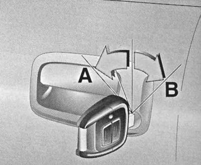
In case of failure, proceed as follows: When unlocking the door, turn the key in the door lock in the direction A, passing the point of resistance, then return it to the vertical position. When locking, - turn in the direction IN until it stops, then return to the starting position.
Replacing the battery
If the operating range of the remote control decreases, the battery should be replaced.
1. Using a small screwdriver, pry up the remote control latch through the special hole.
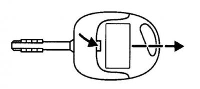
2. Separate the remote control from the key, open its cover.
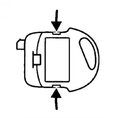
3. Replace the battery.
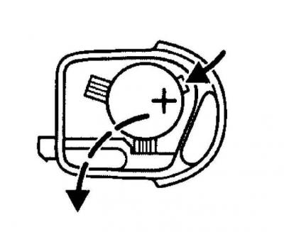
As a replacement, use the same type of element as was previously installed in the remote control. Make sure to observe the polarity of the replacement element.
The battery must be replaced within 3 minutes after opening the remote control cover, otherwise you will have to re-synchronize the transmitter and receiver (see below).
Synchronization of the transmitter and receiver of the remote control device
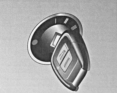
If the remote control device is not functioning properly, it should be re-synchronized: turn on the ignition - the system will be in synchronization mode for 30 seconds; briefly press any of the buttons on the remote control built into the key head. Successful completion of the synchronization process is confirmed by a single activation of the door lock actuators.
Ignition Switch/Steering Column Lock
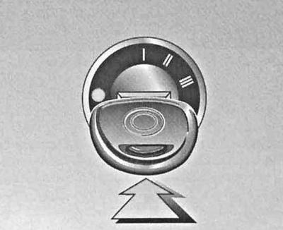
The ignition switch is located on the right side of the steering column. The key can be in one of four positions in the lock:
LOCK (0) — lock
ACC (I) - auxiliary consumers of electrical energy (parking position)
ON (II) — ignition is on
START (III) — engine start
Position "LOCK" (0) - lock
The key can be inserted into or removed from the lock only in this position. When the ignition key is turned from the "LOCK" (0) position to the "ACC" (I) position, the steering column is unlocked. In order to turn the key from the "ACC" (I) position to the "LOCK" (0) position, it is necessary to first press it slightly, slightly pressing it into the lock. In addition, on models equipped with an automatic transmission, an additional condition for allowing the start is the mandatory transfer of the selector lever to the "P" position.
The steering column lock is activated automatically when you try to turn the steering wheel after removing the key from the ignition switch.
Steering column lock sometimes makes it impossible to turn the key in the ignition. In this situation, you should slightly turn the steering wheel in one direction or another (in order to relieve the load), while simultaneously turning the key in the lock.
Never remove the key from the ignition while driving! This will inevitably lead to the steering column locking and loss of control. Remove the key from the ignition only after the car has come to a complete stop!
Position "ACC" (I) - parking
In this position of the ignition key, the operation of auxiliary power consumers is ensured (audio system, cigarette lighter, heater fan, windshield wipers, etc.).
Position "ON" (II) - ignition is on
The ignition key is kept in this position all the time while the vehicle is moving, as well as when the engine is idling. At the same time, all systems and additional equipment installed on the vehicle are supplied with electricity. When the key is turned from the "ACC" (I) position to the "ON" (II) position, some of the control lamps located on the vehicle's instrument panel are briefly switched on, confirming the proper functioning of the corresponding control systems.
On some models, turning the key to the "ON" (II) position automatically turns on the headlights (DRL).
Position "START" (III) - start
Turning the key to this position engages the starter. Once the engine has started, release the key and it will automatically return to the "ON" (II) position.
If the vehicle is equipped with an immobilisation system, the engine will not start unless the anti-theft system identifies the key code (see below).
Engine immobilization system
The standard anti-theft system of some models may include an engine immobilization device (simply - immobilizer). The device serves to prevent attempts at unauthorized engine start and is an effective anti-theft device, protecting the car from thieves.
The key head of models equipped with an engine immobilization system contains a microchip that disables the engine immobilizing anti-theft device.
Damage to the microchip may result in loss of the ability to start the engine! Do not allow the keys to become excessively hot, do not leave them exposed to direct sunlight for a long time; try not to drop your keys or place heavy objects on them; avoid exposure to moisture, if the set gets wet, gently wipe it dry with a soft cloth.
There are no replaceable power elements for the microchip - do not attempt to disassemble the key head on your own under any circumstances!
The engine of a car equipped with an immobilizer can only be started with an ignition key equipped with a built-in microchip. A special code is encrypted in the microchip, and the anti-theft system disables the lock only if it is recognized. An attempt to start the engine with any other key or master key results in the engine starting circuit being disabled.
When the ignition is switched on (the ignition key is turned to the "ON" [II] position), the immobilizer system indicator lamp lights up for a few seconds and then goes out (see Instrument panel, p. Engine pre-glow control lamp (diesel models)). Flashing indicator indicates that the system did not identify the key code. In this case, you must turn off the ignition (key to position "LOCK" [0]) and remove the key from the lock, then try again.
There is a possibility that the system will not recognize the code of the key in the ignition switch if there is another key with a built-in microchip nearby. For reliable code identification, we recommend keeping each key on a separate bunch.
If the system repeatedly refuses to identify the key code, contact the vehicle manufacturer's service station.
The immobilizer indicator lamp also flashes when the ignition key is turned from the "ON" (II) position (ignition on) to position ACC (I) (parking) or LOCK (0) (steering column lock).
Do not attempt to make any changes or additions to the immobilizer design. This may disrupt the normal operation of the vehicle's electronic systems and make it uncontrollable.
If you lose the key and cannot start the engine, contact the vehicle manufacturer's service station.
Enabling/disabling the anti-theft alarm
Turning on
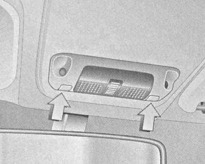
The anti-theft alarm system monitors attempts to unlock the hood, all doors, lid and trunk, in addition, the system includes volumetric sensors inside the cabin, as well as tilt / impact sensors. In addition, attempts to use the ignition switch are blocked separately. It is possible to disable the cabin volume sensors (except Convertible Soft Top models), which allows you to leave children and pets in a locked car. To disable the sensors, turn off the ignition, then simultaneously press the push-button switches of both navigation lamps of the main interior light - the control LED of the anti-theft alarm should be activated for 10 seconds. Then, within 10 seconds, you should lock the doors and activate the alarm (see below).
Make sure that the hood and trunk lid are also locked. When the alarm is triggered, an acoustic signal is activated (3 signals from volume sensors, maximum 10 signals from other sensors) and the direction indicators start flashing.
The maximum duration of the siren operation is 30 seconds, the flashing of the direction indicators continues for up to 5 minutes.
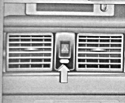
Activation of the anti-theft alarm is accompanied by the activation of an LED built into the instrument panel directly under the hazard warning switch.
The LED operating mode allows you to obtain the following information about the state of the controlled elements:
Within the first 10 seconds after the alarm is activated:
- LED lights continuously: Control, power-on delay
- LED is blinking: Any of the controlled locks is not locked or the system is faulty
10 seconds after the alarm is activated:
- LED blinking: Anti-theft alarm activated
- LED lights continuously for 1 second: Function is disabled.
If the anti-theft alarm system malfunctions, take the vehicle to the manufacturer's authorized service station (Opel).
To activate the anti-theft alarm, lock the driver's door with the key (see above. Unlocking and locking doors with a key from outside the car), then within 10 seconds return the key to the vertical position and turn it to the lock position again. When using the remote control, within 10 seconds after locking the locks, press the button again.
Disconnection
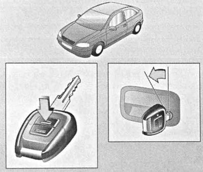
The anti-theft alarm is deactivated automatically when the car doors are unlocked using the key or the remote control (see above. Unlocking and locking doors with a key from outside the car and Remote control).
Unlocking and locking the tailgate/trunk lid
General rules for using the lock
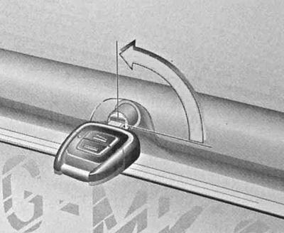
To lock the trunk, turn the key in the trunk lid lock to the vertical position. The horizontal position of the lock cylinder corresponds to the unlocked state of the lid.
When the cylinder is in a horizontal position, the trunk lid lock is activated using the remote control.
If the key is turned to the horizontal position after unlocking the doors with the remote control, the trunk remains locked.
When the lock cylinder is in the vertical position, the trunk remains locked even when the doors are unlocked using the remote control.
It is not possible to activate a single locking device from the tailgate/trunk lid lock.
On Convertible models, unlocking the trunk is only possible when the convertible top is in one of its extreme positions (open or closed) provisions.
To close the trunk, a handle or loop is provided on the inside of its lid/door.
Unlocking the trunk with centrally locked doors
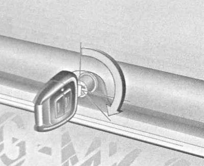
To unlock the trunk with the doors centrally locked, turn the key in the lock from a vertical or horizontal position to the right until it stops, overcoming resistance.
To protect against accidental locking, it is not possible to remove the key from the lock in this position. Returning the key to its original position (vertical or horizontal position causes the lock to lock).
When the cylinder is in a horizontal position, the trunk can only be opened by command from the remote control.
Hood
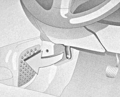
The hood latch release handle is located on the left under the vehicle's instrument panel, with a pictogram on top. To release the latch when unlocking the hood, pull the handle toward you.
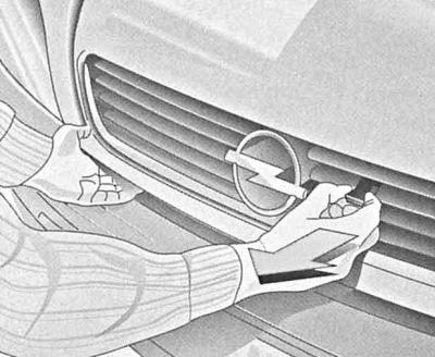
To open the hood after releasing the latch, you must remove the safety lock. The lock release loop is located under the decorative radiator grille, to the right of the center.
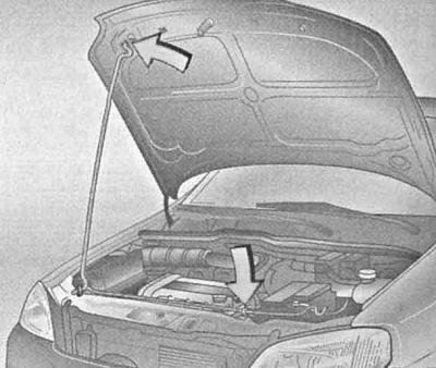
To fix the hood in the open position, a special stop bar is provided, which is inserted into a plastic-lined groove on the bottom side of the cover. Before closing the hood, make sure that the support bar is securely fixed in its holder.
To close, lower the hood to the bottom position, leaving a gap of about 10 centimeters, then release it - after the lock snaps into place, the release loop of the safety lock should not protrude from the radiator grille. To check the reliability of the hood lock in the closed position, pull it up by the front edge.
To avoid damaging the paintwork, do not press the loosely closed hood with your hands; the correct way to open it again is to try to slam it shut by releasing it from a small height.
Fully automatic convertible top (convertible models)
Control by means of a key switch on the instrument panel
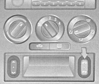
The push-button switch for controlling the operation of the electric convertible top on Convertible models is located in the center of the instrument panel below the control panel for the heating/ventilation/air conditioning systems. The drive can only be activated when the vehicle is stationary.
Pressing the control button when the parking brake is not securely engaged causes the warning buzzer to sound.
Opening
Set the parking brake, turn on the ignition. Make sure there are no foreign objects on the shelf in front of the rear window and in the recess of the convertible top cover. To move the top to the open position, press the section of the switch marked with a pictogram. Completion of the procedure is confirmed by the sound signal.
Closing
Make sure the parking brake is securely engaged. Turn on the ignition. Press the section of the switch marked with a pictogram and hold it down until the convertible top is completely closed. Completion of the procedure is confirmed by the sound of a signal.
Control via remote control and driver's door lock
Activation of the drive is only possible when the vehicle is stationary.
Pressing the control button when the parking brake is not securely engaged causes the warning buzzer to sound.
Opening
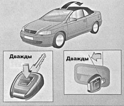
Set the parking brake. Make sure there are no foreign objects on the shelf in front of the rear window or in the recess of the convertible top cover. Unlock the driver's door using the key or the remote control (see above), then hold down the button on the remote control, or turn the key in the driver's door lock to the left and hold it in this position. Completion of the procedure is confirmed by the sound of a signal.
Closing
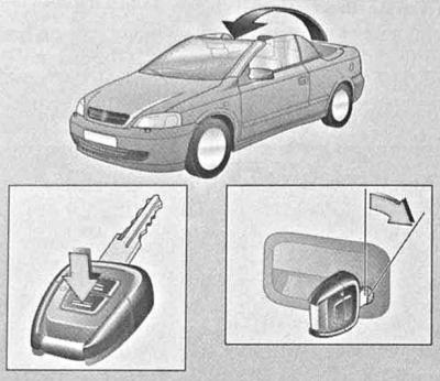
Make sure that the parking brake is securely engaged. Hold down the "=" button on the remote control, or turn the key in the driver's door lock to the right and hold it in this position. Completion of the procedure is confirmed by the sound signal.
At the same time, the glass of unclosed windows will also be raised.
Procedure to follow in case of failure of the electric drive of the convertible top
If the electric drive fails to function, the convertible top is closed in the following order:
1. Make sure the parking brake is securely engaged.
2. Lower all windows using the main switch on the driver's door (see above).
3. Turn off the ignition and remove the key.
4. Open the luggage compartment lid and push the convertible top release lever located on the left forward.
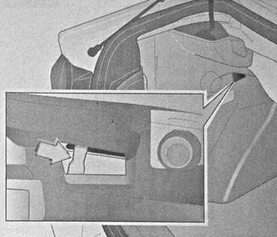
5. Remove the roof support bar from the toolbox.
6. Close the trunk lid and make sure it is securely closed.
7. Slide the trim forward and, overcoming resistance, lift the convertible top cover.
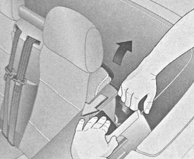
8. Secure the casing in the raised position using the spacer bar.
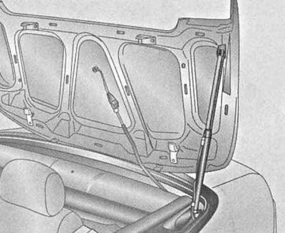
9. Using a screwdriver, loosen and remove the manual drive cover in the middle of the rear shelf.
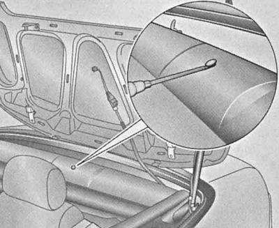
10. Remove the special handle from the storage or tool box, install it in the manual drive socket and turn it to the left until it stops: the locking hooks on the front edge of the roof should open.
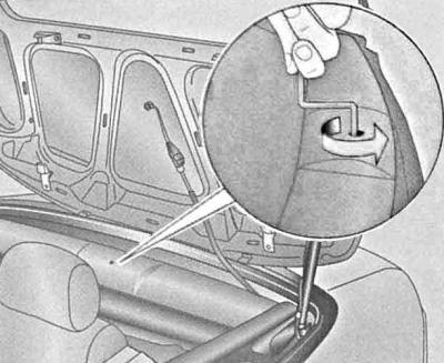
11. Pull the folding handle upwards.
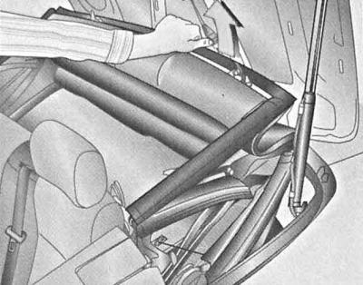
12. When pulling out the top, make sure that the link above the door glass enters its guide - if the required alignment does not occur, then the drive handle was not turned to the left all the way: fold the cover and repeat the procedure.
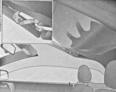
13. Fold up the rear edge of the convertible top, remove the spreader bar and fold the cover, then lower the rear section of the roof again, covering the cover, finally carefully press down the front edge of the roof, lowering it to a position just above the windscreen frame.
Attempts to lift the roof after completing this procedure may result in damage to it!
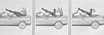
14. Insert the handle into the upper drive slot and rotate it to the right until the cover is completely closed.
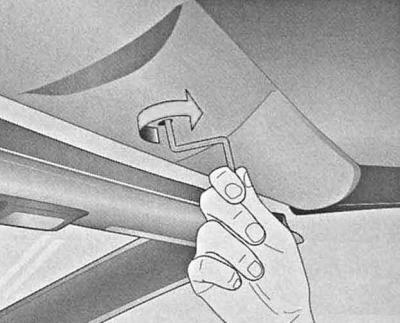
15. Press on the front edge of the roof to ensure it is closed correctly.
16. Once the convertible top has been closed, it must not be folded back manually. To correct the fault, take the vehicle to an authorized Opel service station.
Semi-automatic convertible top (convertible models)
Opening
The convertible top must only be opened when the vehicle is stationary.
1. Make sure the parking brake is securely engaged.
2. To release the convertible roof lock, fold the locking lever from the recess in the frame to the working position and turn it to the right until it stops.
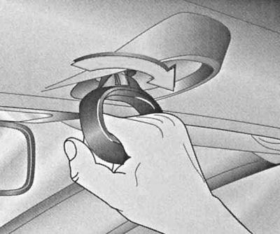
3. Move the front edge of the convertible top up 20 centimeters and return the locking lever to its original position.
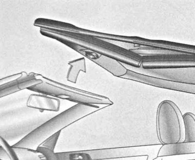
4. Turn on the ignition and fold the roof using the key switch on the instrument panel (see above. Control by means of a key switch on the instrument panel).
Closing
The top is closed in the reverse order of opening.
Procedure to follow in case of failure of the electric drive of the convertible top
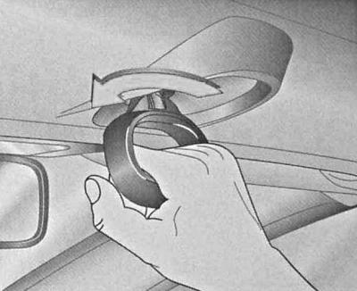
See above. Procedure to follow in case of failure of the electric drive of the convertible top with the only difference being that the roof is fixed in the raised position using a locking lever.
Installing and removing the windscreen (convertible models)
Installation
The windscreen serves to reduce air turbulence, eliminate drafts and reduce background noise when driving with the top open.
1. The wind deflector is stored in the folded position in the luggage compartment of the car. The deflector is inserted into the side guides and secured on the left and right with pin latches. To release the deflector, turn the latches in their sockets. After pushing the released deflector back, remove it from the luggage compartment.
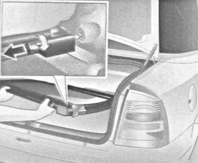
2. Insert the wind deflector guide strips into the receiving slots located between the rear seat head restraints.
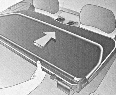
3. Rotate and secure the pin holders on the sides of the screen, then align the screen.
Removal
The screen is removed in the reverse order of its dismantling.
Electric sunroof
Hatchback, Sedan and Station Wagon models
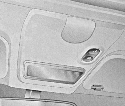
The electric drive of the sunroof functions only when the ignition is on. The switch for controlling the electric drive is located on the overhead console behind the interior light.
Sliding the hatch cover
To move the hatch to a comfortable position, press the icon marked with
 section of the switch. In this position, the noise background caused by the oncoming air flow is minimized. To open the hatch more completely, press the switch again.
To close the hatch, hold down the button marked with the icon
 switch section.
Folding back the hatch cover
The closed hatch cover is opened by pressing the button marked with the pictogram
 switch section.
The lid is returned to the closed position by pressing the icon marked with
 switch section.
Closing the sunroof when leaving the car
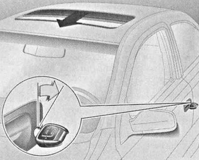
To close the sunroof if it is left open, hold the key in the driver's door lock until the sunroof is completely closed.
At the same time, the closing of windows left open should also occur.
Procedure to follow in case of electric drive failures
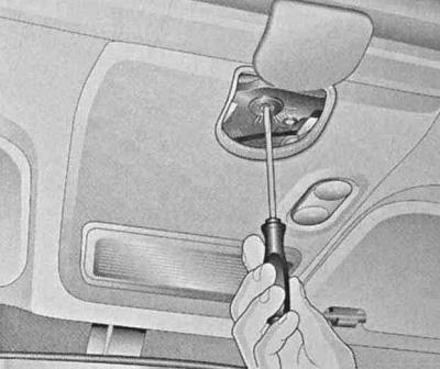
If the sunroof electric drive fails, slide the cover located at the rear of the overhead console, then use a screwdriver to push inward the center spring-loaded part of the drive shaft, then rotate the shaft until the sunroof cover is completely closed.
Coupe Models
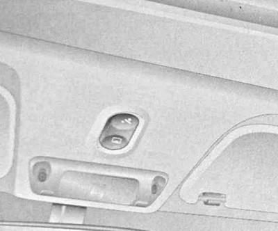
The electric drive of the sunroof functions only when the ignition is on. The switch for controlling the electric drive is located on the overhead console behind the interior light.
The principle of control of the electric drive operation
The principle of control of the electric drive operation is similar to that described above for the Hatchback, Sedan and Station Wagon models (see above p. Hatchback, Sedan and Station Wagon models).
Procedure to follow in case of electric drive failures
If the electric drive of the upper hatch fails, release the cover locks using the ignition key. Remove the special handle with different end designs from the glove compartment.
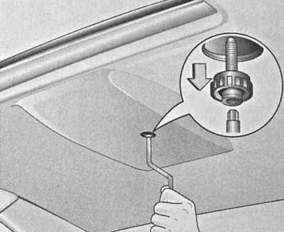
Using one end of the handle, loosen the Allen screw. Remove the screw together with the serrated plastic washer. Engage the opposite end of the handle with the sunroof drive shaft and rotate it until the sunroof is completely closed.
Window lifters
Manual window lifts
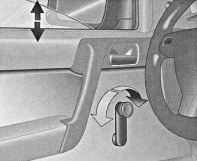
The rotary handles of the drive are located on the inner sides of the corresponding doors.
Electric windows
On appropriately equipped models, the electric window lifts only operate when the ignition is on.
Each door of the car has a switch designed to control the operation of the electric drive of the window regulator of that door. Drive (lowering/raising) glass is carried out by pressing the corresponding section of the key. A short press on the key allows for a step-by-step opening/closing of the glass. To automatically move the glass to the extreme (upper or lower) position, the corresponding part of the key should be held down for a longer period of time, pressing the key again will stop the glass. The functional readiness of the switches is confirmed by built-in control lamps.
A.
B.
C.
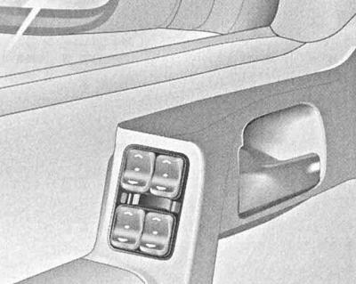
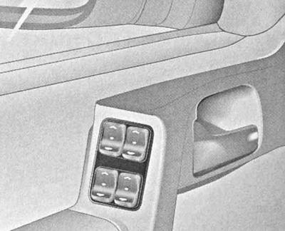
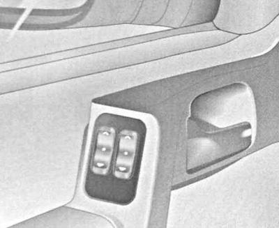
On the left side of the driver's door armrest is the central control panel for the electric window lifters of all the car's doors. The principle of operation of the switches is similar to that described above for individual door switches.
A — Main switch for controlling the operation of the electric window lifters on the armrest of the driver's door (two-door models)
B — Main switch for controlling the operation of the electric window lifters on the armrest of the driver's door (four-door models)
C — Main switch for controlling the operation of the electric window lifters on the armrest of the driver's door (four-door models with built-in lock)
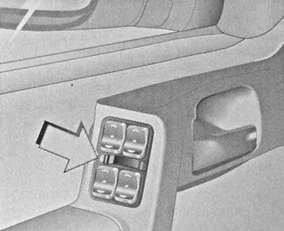
On some models, an additional slide switch is built into the main switch assembly, allowing the passenger door window drive to be blocked from the individual switches.
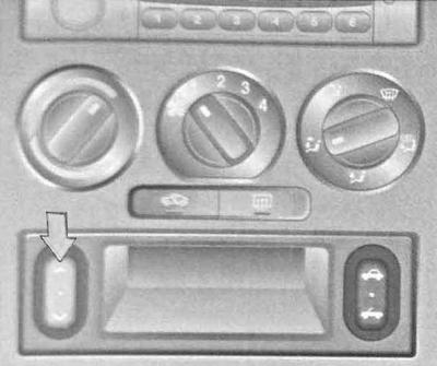
An additional switch is also provided, with which centralized opening/closing of all windows can be performed. The switch is mounted in the central part of the instrument panel and is located under the control panel of the heating/ventilation/air conditioning systems, to the left of the storage pocket. Activation of the lock is accompanied by the switching on of the red indicator lamp, the lighting of the green one indicates that the lock is deactivated.
If resistance to lifting the glass occurs in the second half of its travel, the operation of the window lifter is immediately suspended, which prevents the driver and passengers from getting injured as a result of pinching their hands or other body parts.
If the glass stops moving due to icing, you should press the corresponding button several times.
To activate the power windows after a power failure/excessive drop in battery output voltage, close all doors, turn on the ignition and hold down the switch keys for each door in turn.
It is also possible to close all windows to the closed position when leaving the car using the key or the remote control - see above. Unlocking and locking doors with a key from outside the car and Enabling/disabling the anti-theft alarm — Disconnection).
Visitor comments