
Speed stages are achieved by connecting resistances of different sizes (or their serial connection). The resistors are included in the positive wire to the blower motor. Earth connection is permanent, while positive contact «getting better» or «getting worse».
Removing the blower
The blower motor is balanced with the fan, so both parts can only be replaced as an assembly.
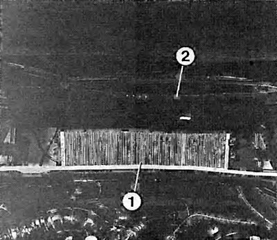
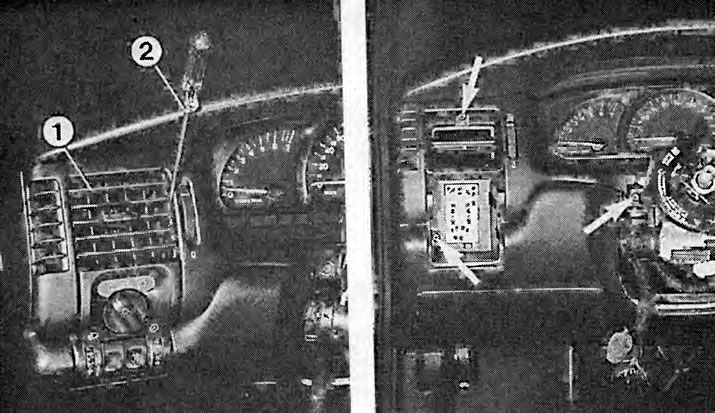
After the service cover is lifted (2) and four clips are released, the dust filter can be removed from the cutout (1).
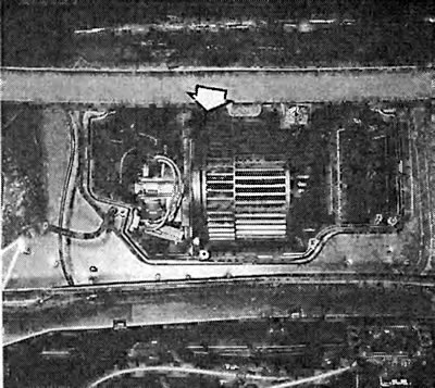
The photo shows an exposed blower motor. The engine is located, mounted on the side, in the water trap box. When dismantling, remove the air blower motor from the guides.
Remove the wiper arms and unscrew the plastic nuts from the wiper rollers.
Remove the rubber seal from the front wall.
Remove the water repellent at the ends under the windshield from the clips and then from the water collection box.
Unscrew the fixing screws and remove the wiper motor.
Release the dust filter retainers and remove it from the housing.
Remove the vacuum hoses from the inside and outside of the dust filter housing.
Unscrew the fixing screws and nuts. Slide the dust filter housing to the right in the direction of travel and remove it from the water collection box.
Unscrew the blower cover, release the four locking tabs and remove the cover from the lower part.
Disconnect the multi-pin connector at the blower motor.
Remove the blower motor from the guides. If necessary, additionally release the additional resistance holder.
Dismantling the additional resistance of the air blower
With one faulty additional resistor, the entire holder of additional resistors is replaced. The holder is inserted directly into the supercharger body.
Expose the blower motor, see section on blower motor removal.
First, pull the additional resistance holder up. Then remove the holder from the cutout on the side.
Disconnect the multi-pin wire connector.
Disconnect also on the holder both sockets of a wire to the supercharger engine.
Connect the multi-pin connector to the new resistor holder and install the holder.
Connect both wire connectors.
Removing the heating/ventilation control module
Heating and ventilation switches are not individually replaced. If one switch is faulty, the heating/ventilation control assembly must be changed.
Carefully pry the decorative panel of the heating/ventilation module out of the latches with a screwdriver.
Where necessary, remove all rotary controls from the switches.
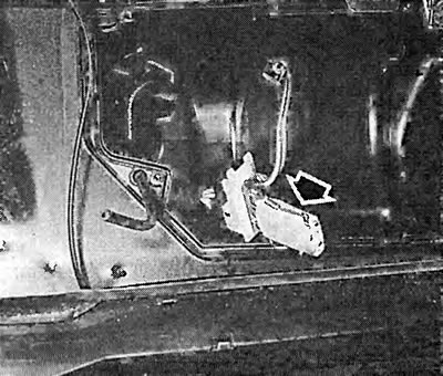
Here you can see the additional resistances of the air blower. Before you can remove the additional resistances, you need to open the blower motor.
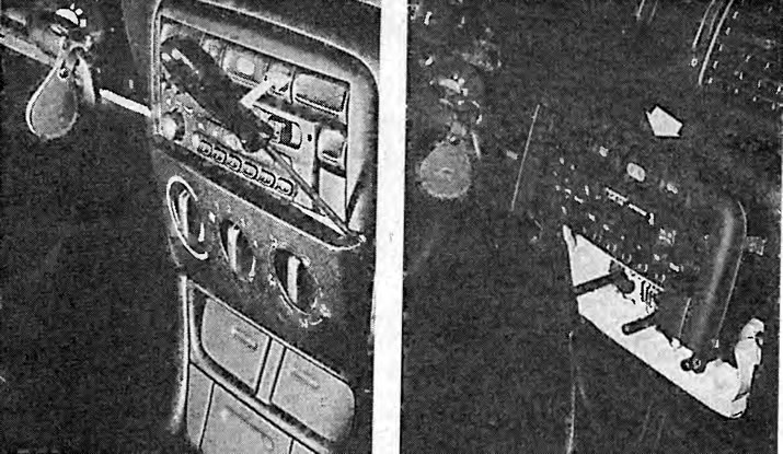
Left: dismantling the heating/ventilation control module. First, as shown, carefully remove the decorative panel from the clips with a screwdriver.
On right: after dismantling the decorative panel, unscrew the switch panel at the bottom and then remove it from the lock at the top.
Unscrew both fixing screws of the switch panel and remove it from the clamp.
Slide the heating/ventilation module up about 1 cm and remove it from the cutout.
Unlock and disconnect the multi-pin connector behind the heating/ventilation module.
Release the clamps and unhook the flexible cables from the regulators.
Remove the heating/ventilation module.
When mounting, insert the rotary adjusters so that the guide lugs in the handles line up with the grooves in the rollers.
Dismantling the heat exchanger
Coolant passes through the heat exchanger, and it looks like a small radiator. On our Vectra, it is located in the passenger compartment air distributor housing.
Drain and save coolant.
In the engine compartment, unlock the quick-release valves and remove both coolant hoses from the heat exchanger. To unlock the shutters, press the safety locks and slide back the retaining ring on the shutter.
Drain any remaining coolant.
Remove the center console see salon chapter.
Unscrew the upholstery support of the dashboard.
Remove the rear footwell air distributor housing.
Remove from clips or unscrew facing of the heat exchanger and remove from the case of the distributor of air.
Remove the heat exchanger from the air distributor housing Be careful, coolant flows out!
When installing, pay attention to the correct position of the rubber gasket.
If the fasteners of the heat exchanger lining have been damaged, additionally fasten the lining to the side with four fixing screws.
When connecting the coolant hoses, push the hoses in until you can hear the quick-release fasteners engage.
If the quick release closures are new, the green locking ring should come off the closure. Remove the green blocking ring from the heat exchanger tube.
After installation, fill the cooling system with liquid and remove air from it.
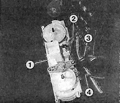
Reverse side of the heating/ventilation control module (1). When dismantling as described in the text above, remove the flexible cables (2 and 4) and disconnect the multi-pin connector (3).
Left: dismantling the left liner (1) mixed air flow nozzles. Insert screwdriver (2) left and right between body and nozzle insert. Disconnect the hooks of the mixed air nozzle and remove from the housing.
On right: dismantle the left housing of the mixed air nozzle. Three mounting screws are visible here (arrows), with which the case is screwed to the dashboard.
Removing the middle air nozzle
Remove the dashboard trim, see chapter «Tools and devices».
Remove the air nozzle insert. To do this, turn the mixed air nozzle down as far as it will go.
Insert a screwdriver on the left and right between the housing and the nozzle insert.
Unhook the mixed air flow nozzle and remove it from the housing.
Dismantle the opposite nozzle in the same way.
Unscrew the two fixing screws in the housing of the mixed air nozzles and the fixing screw on the left side and remove the housing from the cutout in the dashboard.
During installation, insert the air nozzle inserts in such a way that the connecting bridge of the plates faces downwards. Also pay attention to the correct location of the side rubber support. Insert the nozzle by turning the side notches to the guide pins in the body and press.
Removing the left air nozzle
Dismantle facing of a steering column, see the chapter «Salon».
Remove the light switch, see chapter «Tools and devices».
Remove the nozzle insert as described in the previous section.
Unscrew the three fixing screws of the nozzle body and remove the body from the cutout in the dashboard.
Use a screwdriver to unblock the plug connector of the light switch and pull it out from the side down.
When installing, push the connector block until it locks into place.
Removing the right air nozzle
Remove the glove box.
Remove the mixed air nozzle, see section «Removing the middle air nozzle».
Unscrew the three fixing screws of the mixed air nozzle housing and remove the housing from the cutout in the dashboard.
When mounting, press the nozzle body into the cutout until it locks into place.
Insert the air nozzle insert so that the plate connecting web is facing down. Also pay attention to the correct location of the side rubber support. Insert the nozzle by turning the side notches to the guide pins in the body and press.
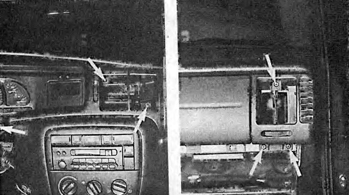
Left: remove the middle mixed air nozzle. The arrows indicate the three mounting screws that secure the mixed air nozzle body to the dashboard.
On right: remove the right mixed air nozzle. The arrows show the three fixing screws of the right mixed air nozzle. First remove the glove box and the mixed air nozzle.
Visitor comments