


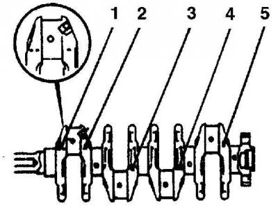
Place of marking of the bore diameter of bearings of a 1.7 l diesel engine
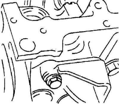
Diesel engine 1.7 l
To select the working clearance of bearings, 4 different liners are used, which are designated by a color mark on the end face. The color of the mark indicates the thickness of the liners and increases sequentially depending on the color: green, brown, black or blue.
If it is necessary to replace a bearing shell, first check and record the identification mark located on the crankshaft adjacent to each bearing journal.
Record the main bearing bore size identification markings located on the lower mating surface of the rear of the engine block.
According to the bearing bore code and crankshaft journal code, select a new main bearing shell using the following table. Crankshaft codes are on the left side, bearing bore codes are on the top. The bearing type is selected at the intersection of the two lines.
|
1
|
2
|
3
| |
|
line
|
black
|
brown
|
green
|
|
lines
|
blue
|
black
|
brown
|
Other engines
Both standard and undersized crankshaft main bearings can be used. The required bearing size can be determined after measuring the crankshaft journal.
Checking the bearing operating clearance
1. Clean the rear of the bearing shell and its installation location in the cylinder block and main bearing caps.
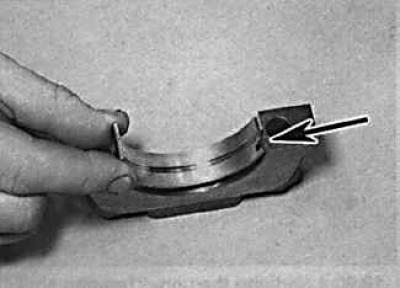
2. Install the inserts in their places, while the protrusion on the insert should be aligned with the groove on the cover.
3. One method, which requires a micrometer to measure bore diameters, is to install the main bearing caps with the bearing shell on the cylinder block and tighten them to the specified torque. Measure the inside diameter of each assembled pair of bearing shells. Measure the diameter of each crankshaft journal. Subtract the corresponding crankshaft journal diameter from the measured bearing diameter.
4. Second (and more accurate) the method is to use a product known as Plastigage. This is a round plastic rod that is compressed between the bearing shell and the crankshaft journal. After removing the main bearing cap, the deformed plastic rod is measured with a special template that is included with the Plastigage. The procedure for using Plastigage is as follows.
5. Install the crankshaft without lubrication on the liners installed in the cylinder block. The crankshaft journals and liners must be completely clean and dry.
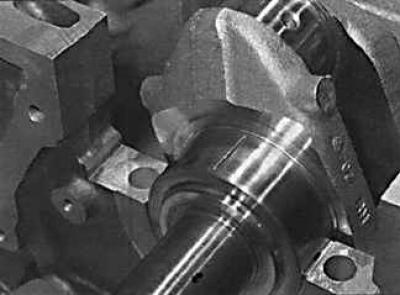
6. Cut a few pieces of Plastigage plastic rod (they should be slightly shorter than the width of the main bearings) and install on each crankshaft journal.
7. Install the caps with the lower liners and tighten the mounting bolts to the specified torque. Do not rotate the crankshaft during the Plastigage clearance measurement.
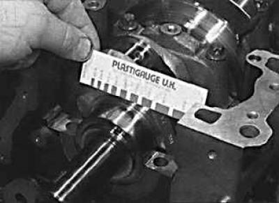
8. Unscrew the liner mounting cover, remove it and apply a scale ruler to the deformed plastic rod. By comparing the width of the deformed plastic rod with the reference width on the scale ruler, determine the size of the gap.
9. Finally, thoroughly clean away any traces of Plastigage from the bearings and crankshaft.
Visitor comments