


Contents: Ignition switch ⬇ Turn signal and wiper switches ⬇ Instrument panel switches ⬇ Light switches and fog lights ⬇ Hazard warning switch ⬇ Interior and luggage compartment…⬇ Window lift switch ⬇
Ignition switch
Removal and installation
1. Remove the steering wheel.
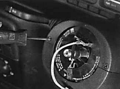
2. Unscrew the tilt control arm and remove the two screws from the front end and three screws from the bottom of the steering column cover.
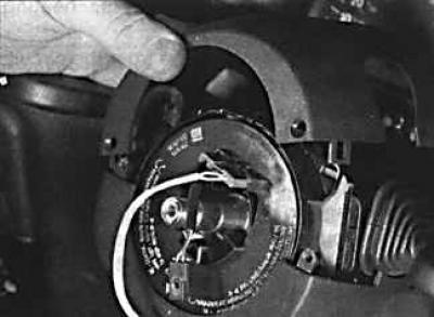
3. Remove the steering column covers.
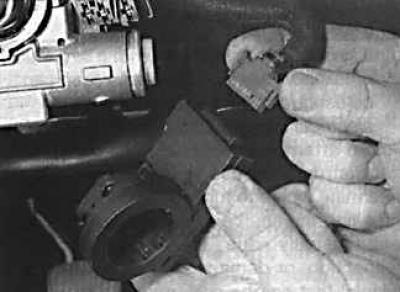
4. Remove the immobilizer transceiver from the ignition switch and disconnect the electrical connector from it.
5. Insert the ignition key and turn it to position 1.
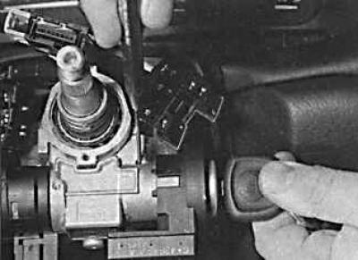
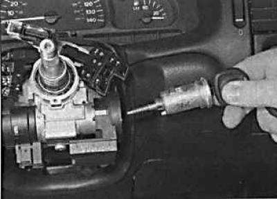
6. Using a thin-bladed screwdriver, press the locking pin through the hole in the top of the steering column (photo on the left), then remove the lock cylinder by the key (photo on the right).
7. When installing the lock cylinder, insert the lock cylinder into the lock body until the lock pin locks the lock cylinder. Then turn the ignition key to position 0 and remove the key.
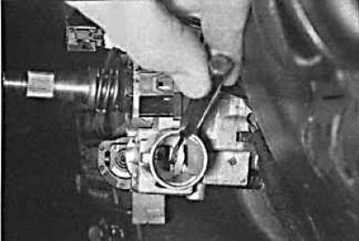
8. If the steering column lock pin has fixed the steering shaft from turning when the ignition lock cylinder is removed, it is impossible to insert the ignition lock cylinder. In this case, use a screwdriver to move the steering column lock before installing the ignition lock cylinder.
9. To remove the ignition switch contact group, remove the ground wire from the battery and remove the ignition switch cylinder.
10. Press the small cylinder, turn and remove the contact group from the ignition switch.
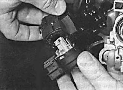
11. Disconnect the electrical connector from the ignition switch assembly.
12. Installation is carried out in the reverse order of removal.
Turn signal and wiper switches
The turn signal and windshield wiper switches are removed in a similar manner.
Removal and installation
1. Remove the steering wheel.
2. Remove the steering column covers by unscrewing the tilt control arm and removing the two screws from the front end of the upper cover and the three screws from the base of the lower cover.
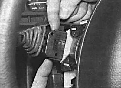
3. Remove the switch from its socket.
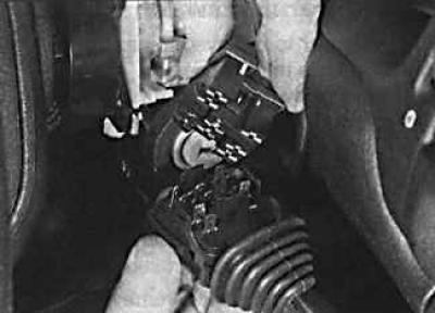
4. Disconnect the electrical connector from the switch.
5. Installation is carried out in the reverse order of removal.
Instrument panel switches
Removal and installation
1. Insert a narrow screwdriver between the switch and the instrument panel, placing a rag or paper underneath to avoid damaging the surface of the panel.
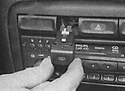
2. Carefully remove the switch, alternately inserting the screwdriver from the top and bottom.
3. Disconnect the electrical connector from the switch.
4. Installation is carried out in the reverse order of removal.
Light switches and fog lights
Removal and installation
Material copied from this resource (OPELBOOK)
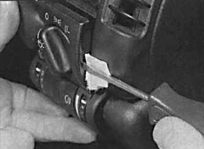
1. Insert a narrow screwdriver between the switch and the instrument panel, placing a rag or paper underneath to avoid damaging the panel surface. If the switch is installed very tightly, insert the screwdriver alternately from below and above and remove the switch. To remove the fog light switch, release the key.
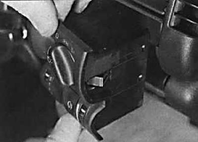
2. Remove the switch from the instrument panel.
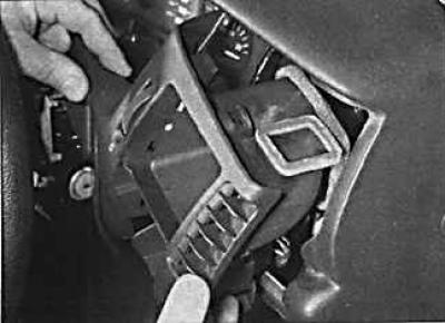
3. If it is necessary to remove the switch cover, remove the air duct, then unscrew the screw and remove the cover.
4. Installation is carried out in the reverse order of removal.
Hazard warning switch
Removal and installation
1. The switch is easier to remove if the switch button is pressed. in the luggage compartment. Unscrew the spare wheel holder.

2. Insert a narrow screwdriver between the switch and the instrument panel and pull out the switch, alternately placing the screwdriver from the top and bottom.
3. Installation is carried out in the reverse order of removal.
Interior and luggage compartment lighting switches
Removal and installation
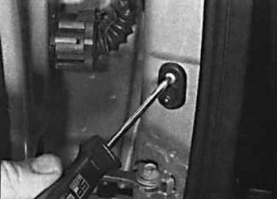
1. Open the door, unscrew the screw that secures the switch and remove it from the door frame. Tie a cord to the wires that go to the switch.
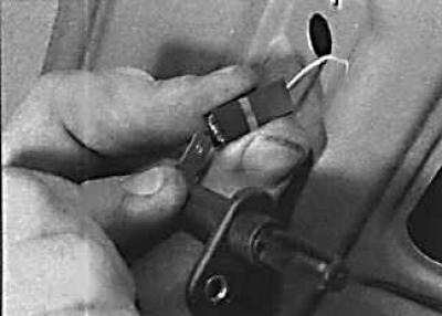
2. Disconnect the electrical connector from the switch.
3. Installation is carried out in the reverse order of removal.
Window lift switch
Removal and installation
1. Remove the gear shift lever trim from the center console.
2. Disconnect the electrical connector from the switch.
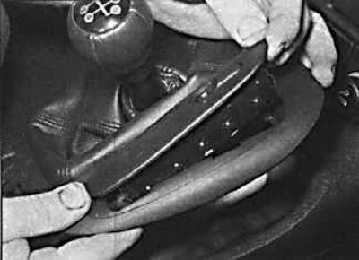
3. Unscrew the two screws and remove the decorative cover together with the switch.
4. Remove the switch from the trim panel.
5. Installation is carried out in the reverse order of removal.
Visitor comments