


Air conditioning system
The air conditioning system diagram is shown in the figure 9.20.
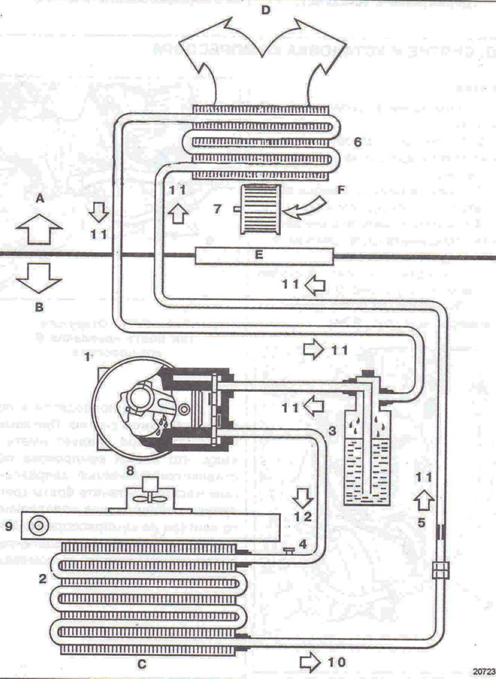
Figure 9.20. Air conditioning system diagram: A - Car interior; B - Engine compartment; C - Outside air; D - To the air mixing unit; E - Engine compartment partition; F - Outside or recirculated air; 1 - Compressor; 2 - Capacitor; 3 - Receiver-dryer; 4 - Pressure sensor; 5 - Reducer; 6 - Evaporator; 7 - Electric fan of the heating and ventilation system; 8 - Electric fan of the engine cooling system; 9 - Engine cooling system radiator; 10 - High pressure refrigerant; 11 - Low pressure steam; 12 - High pressure steam.
Materials used (cars with F9Q engines)
Compressor - DELPHI HARISSON V5.
Compressor oil - DELPHI HARISSON (PLANETELF PAG 488 220 cm³ + 15).
Refrigerant - R 134a (700 + 25 grams).
Removal and installation the capacitor
Removal
1. Disconnect the battery.
2. Using a filling station, drain the refrigerant from the refrigeration circuit.
3. Remove the radiator grille, headlights, engine sump guard, fender liner fastenings to the bumper, unscrew the bolts of the inner fender protective pads attached to the bumper, remove the front bumper (together with an assistant).
4. Disconnect the pressure sensor.
5. Disconnect the pipes from the condenser.
6. Release the radiator from the spring holders at points A and B, then lift the condenser slightly (figure 9.21a, b). Remove the capacitor through the bottom.
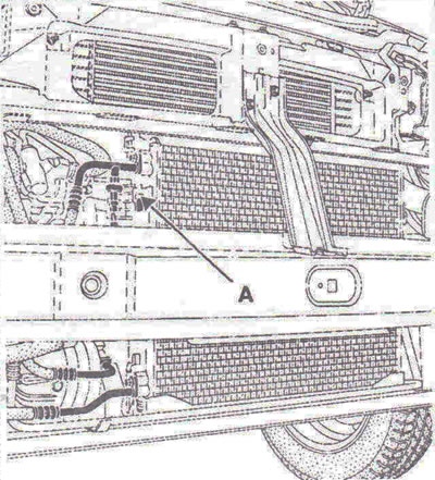
Figure 9.21a. Release the radiator from the spring holders at points A...
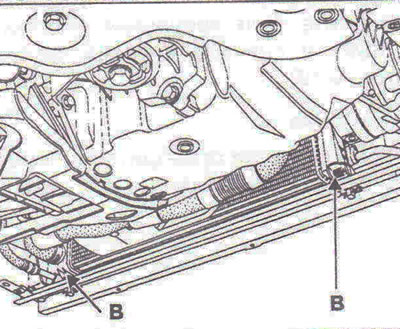
Figure 9.21b....and B, then lift the capacitor slightly.
Installation
7. Check the reliability of the condenser fastening. Installation is carried out in the reverse order of removal.
Visitor comments