


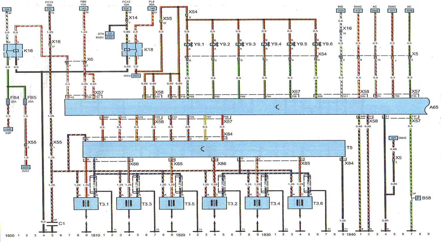
Key to diagram 5
Components
- A65 - Engine/Fuel Injection System Control Unit Multec and Drive train
- B58 - Power steering fluid pressure sensor
- C1 - ignition coil
- FB4 - fuse
- FB5 - fuse
- K16 - fuel pump relay
- K18 - Engine control unit relay
- T3.1 - ignition coil of cylinder No. 1
- T3.2 - ignition coil of cylinder No. 2
- TZ.Z - ignition coil of cylinder No. 3
- T3.4 - ignition coil of cylinder No. 4
- T3.5 - ignition coil of cylinder No. 5
- T3.6 - ignition coil of cylinder No. 6
- T5 - ignition coil unit
- Y9.1 - cylinder #1 injector
- Y9.2 - cylinder #2 injector
- Y9.3 - cylinder injector #3
- Y9.4 - cylinder injector #4
- Y9.5 - cylinder injector #5
- Y9.6 - cylinder #6 injector
Connections
- X5 - Engine Wiring Harness
- X6 - Engine Wiring Harness
- X14 - Instrument cluster and engine compartment wiring harness
- X16 - Instrument cluster and engine compartment wiring harness
- X54 - Engine and Fuel Injector Wiring Harness
- X66 - Engine control unit wiring harness
- X55 - Engine Wiring Harness
- X57 - Engine control unit wiring harness
- X58 - Engine control unit wiring harness
- X84 - ignition coil wiring harness
- X85 - ignition coil wires
- X86 - ignition coil wires
Points of "mass" (-)
- 5 - left side of the engine compartment
- 8 - engine, right side
- 9 - engine, left side
- 11 - Engine, left side
Abbreviations
- 6VDI - 6VDI engine
- 15 - ignition voltage
- 15A - 15 amps
- 30 - permanently energized terminal 30
- ZOA - 30 amps
- AC - air conditioner
- DIAG - diagnostic connector
- FB6 - fuse FB6
- FC12 - fuse FC12
- FC13 - fuse FC13
- FL6 - main fuse FL6
- INS - instrument cluster
- KSP - fuel pump
- STA - Starting and Charging System
- WEG - speedometer
Open large image in new tab →
Scheme 5. Multec and Drive train fuel injection system and engine control unit. Cars with 6VDI petrol engine.
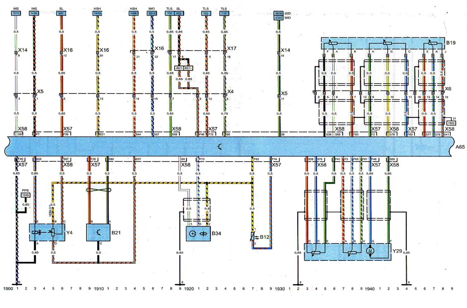
Key to diagram 5 (continuation)
Components
- A65 - Engine/Fuel Injection Control Unit
- B12 - coolant temperature sensor
- B19 - accelerator pedal position sensor
- B21 - absolute pressure sensor
- B34 - crankshaft position sensor
- Y4 - EGR valve
- Y29 - throttle valve opening angle potentiometer
Connections
- X4 - Engine Wiring Harness
- X5 - Engine Wiring Harness
- X6 - Engine Wiring Harness
- X14 - Instrument cluster and engine compartment wiring harness
- X16 - Instrument cluster and engine compartment wiring harness
- X17 - Instrument cluster and engine compartment wiring harness
- X57 - Engine control unit wiring harness
- X58 - Engine control unit wiring harness
Points of "mass" (-)
- 8 - engine, right side
- 9 - engine, left side
Abbreviations
- 31 - point "mass" (-)
- GID - Graphical Information Display
- HSH - rear window heater
- IMO - immobilizer (anti-theft system)
- INS - instrument cluster
- MID - Multi-information display
- PPS - accelerator pedal position sensor
- SL - brake lights
- TLS - Turn Signal Switch
Open large image in new tab →
Scheme 5. Multec and Drive train fuel injection system and engine control unit. Cars with 6VDI petrol engine (continuation).
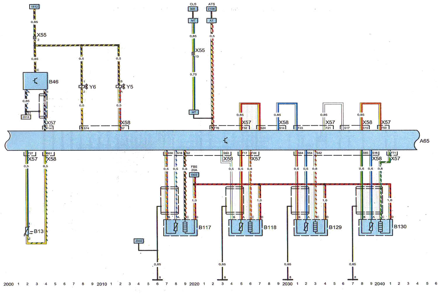
Key to diagram 5 (end)
Components
- A65 - Engine/Fuel Injection System Control Unit Multec and Drive train
- B13 - intake air temperature sensor
- B46 - mass air flow sensor
- B117 - heated preliminary lambda probe
- B118 - main lambda probe
- B129 - heated preliminary lambda probe
- B130 - main lambda probe
- Y5 - fuel tank ventilation valve
- Y6 - EGR valve
- X55 - Engine Wiring Harness
- X57 - Engine control unit wiring harness
- X58 - Engine control unit wiring harness
Points of "mass" (-)
- 8 - engine, right side
Abbreviations
- 20A - 20 amps
- 31 - point "mass" (-)
- AT - automatic transmission
- ATS - Automatic Transmission Mode Switch
- CLS - Clutch Pedal Position Sensor
- FB5 - fuse FB5
- MT - manual transmission
Open large image in new tab →
Scheme 5. Multec and Drive train fuel injection system and engine control unit. Cars with 6VDI petrol engine (end).
Visitor comments